Download
1 / 5
60 likes | 170 Views
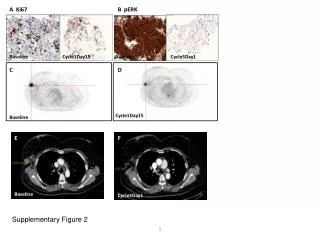
NSTX-U 5 year plan goal: implement cryo -pumping and begin transition to metallic PFCs to support PMI / FNSF next-steps. Long- term goal: a ssess compatibility of high t E and b + 100% NICD with metallic PFCs. Baseline. W is leading candidate material for FNSF/Demo divertor.

E N D
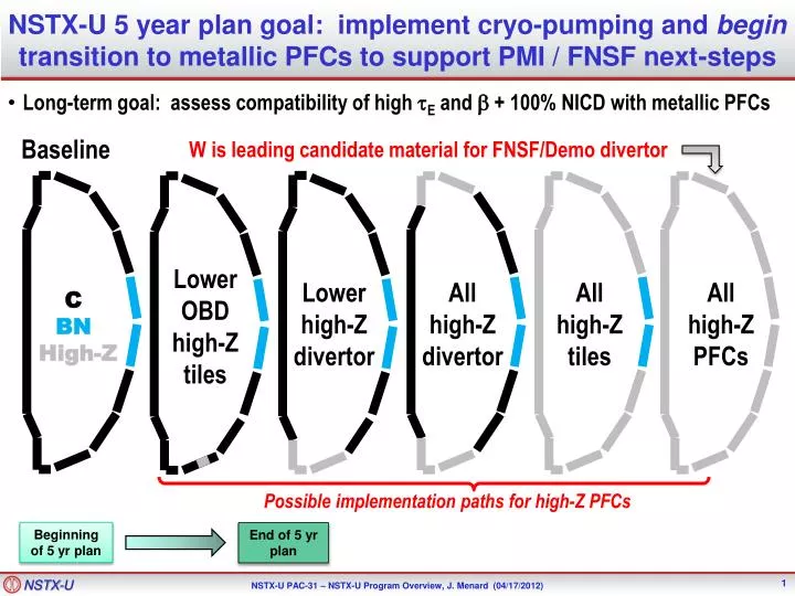
NSTX-U 5 year plan goal: implement cryo-pumping and begin transition to metallic PFCs to support PMI / FNSF next-steps • Long-term goal: assess compatibility of high tE and b + 100% NICD with metallic PFCs Baseline W is leading candidate material for FNSF/Demo divertor Lower OBD high-Z tiles Lower high-Z divertor All high-Z divertor All high-Z tiles All high-Z PFCs C BN High-Z Possible implementation paths for high-Z PFCs Beginning of 5 yr plan End of 5 yr plan
A possible approach • Start with all graphite PFCs: • Most tolerant PFC to high heat flux, disruptions, impurity accumulation • Compare/contrast to previous full C PFC operation of NSTX • Included in NSTX Upgrade project – minimizes cost and time • Implement cryo on bottom outer divertor (bakeable baffle) • Establish density control without lithium coatings • Develop cryo-only scenarios for next-steps, compare to Li coatings • Diagnose pumped plasmas (many divertor diagnostics view bottom) • Reversed-BT field-line pitch not compatible with BES, GPI, tFIDA views • LSN B-drift up is standard / best-diagnosed configuration from NSTX • Put first high-Z PFC tiles at larger R on lower outboard divertor • Begin transition to high-Z PFCs to support PMI / FNSF next-steps • Minimize risk to standard higher-dshapes and scenarios • Assess high-Z tile design(s) tolerance to thermal loads and disruptions • Assess erosion, migration of high-Z materials • Small high-Z area to compare Li on C vs. Mo/W, bakeable mini-LLD • Increase high-Z coverage as plasma/PFC performance permit
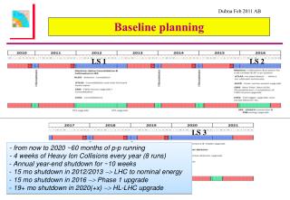
Some implementation decisions for cryo + high-Z PFCsBaseline plan – 2015-2018 Extended outage 2017 2018 2015 2016 Lower risk/slower path • Minimize risk, cost, and time • Avoid mixed PFC materials Or Or Or High-Z PFC(s) Or Cryo • Earlier start on high-Z research • Inform full high-Z divertor decision • Bakeable baffle tile-based LLD • Earlier start on high-Z research • Inform decision on high-Z tile row for cryo-shelf More aggressive path • Inform decision on full high-Z coverage of upper divertor and wall • Full high-Z lower LLD
Long-term decisions for 2019-22 Or Or All high-Z divertors All high-Ztiles Or Or Flowing LLD module Full toroidal flowing LLD
For 5YP, MP groups need to be specific about the ideas that will be considered for how PFCs would be implemented • Example options to be consideredand described are provided below. Can/should reference/quote results/plans from other facilities (JET, EAST, ASDEX) • High heat flux regions (strike-point regions) • W Lamellae or TZM tiles • Intermediate heat flux regions (cryo-baffles, CS midplane) • TZM tiles • Low heat flux regions (passive plates, CS off-midplane) • W-coated graphite