Download
1 / 14
140 likes | 303 Views
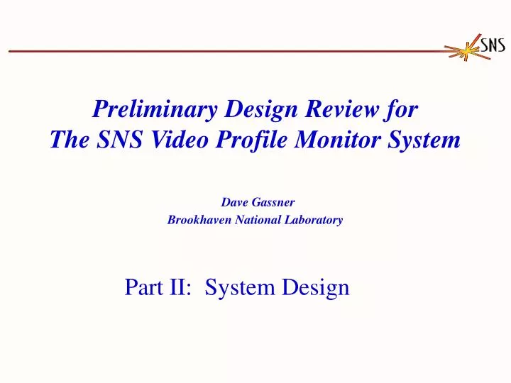
Preliminary Design Review for The SNS Video Profile Monitor System Dave Gassner Brookhaven National Laboratory. Part II: System Design. Part II. System Design. Mechanical designs by: J. Brodowski (Beamline components) S. Bellavia (Camera, ND filter, lens, lamp, mount)

E N D
Preliminary Design Review forThe SNS Video Profile Monitor SystemDave GassnerBrookhaven National Laboratory Part II: System Design
Part II. System Design • Mechanical designs by: • J. Brodowski (Beamline components) • S. Bellavia (Camera, ND filter, lens, lamp, mount) • Based on experience at RHIC, BAF, & AGS fixed target systems. • Radiation hardened components. SNS VPM PDR
VPM Block Diagram Network Rack In Ring Service Building Neutral Density Filter Illumination Lamps Object Lens Video Camera Framegrabber Camera CCU ND Filter Cntrl Lamp Control Quartz Port SNS VPM PDR
SNS VPM Layout Secondary (thick) Foil Camera Cubby Primary (thin) Foil Camera Cubby Estimated Radiation levels The main cause of loss at injection will be nuclear scattering at the thin carbon foil. Uncontrolled loss = 2.5W/m Produces about 250 R/hr at 1 ft. HEBT Beam SNS/AP Tech note 7 Camera to foil distance 5 meters Est. Camera Dose 10’s kR/year SNS VPM PDR
Primary Stripping Foil Assembly Phosphor Screen: • Al2O3, Morgan Matroc, Chromox-6 • 1mm thick • Fiducials for frame grabber reference. • Stripping Foil: • Foil 1 micron thick will heat up to > 2000K. • 1.5” long by 0.5” tall. • Object (beam) will be 0.5” x 0.5” (end of foil) • Viewed via 2.5” ID quartz port at 40o. SNS VPM PDR
Secondary Stripping Foil Assembly Secondary foil: 10mils Carbon-carbon, 3.5” wide 2.5” ID quartz port at 40o View is ellipse 3.125” wide, 2.375 tall. The 2 beams H- & H0 are 2.125” apart on center Phosphor Screen: Al2O3, Morgan Matroc, Chromox-6, 1mm thick Fiducials for frame grabber reference. SNS VPM PDR
SNS Video Foil Hardware Dage 70RV camera, ND filter, lens assembly on rails inside cubby recessed in nearby wall. • Neutral density filter assembly (C-AD): • DC motor drive • Geneva gear with chain • 6 positions (blank, 1, 2, 3, 4, 5) The cubby hole, camera mount, with drawer slides. SNS VPM PDR
Radiation Hardened Components Vacuum Tube Newvicon Video Tube • Video Camera • Dage-MTI 70RVH - Monochrome • Vacuum tube based camera head (no solid state). • Separated camera head & camera control unit. • AGC & Auto pedestal (black) loops in manual mode. • Designed for BNL, used at g-2 target, 60 X 1012 protons at 28 GeV. • 10 M-Rads, no failures. • Neutral Density Filter, BNL design –Rad hard design. • Camera Lens, Fujinon – Mega-Rad dose, 10% transmission loss. • Vacuum port, quartz – Most Rad-hard material. Newvicon Spectral Response SNS VPM PDR
Foil Temperature & Wavelength SNS Primary stripping foil reaches equilibrium temperature 2000K, after about 20us. Newvicon tube Spectral Response 200nm 1000nm SNS VPM PDR
Response & Timing Response Characteristics: Screen: Time constant = 10’s of ms Fluorescence wavelength 700 – 900 nm Radiation Resistance about 1 x 10²⁰ p/cm2 (C Johnson, CERN) Newvicon Tube: Time constant = 10’s of ms Saturation recovery = 100’s of ms Stripping Foil design continues. System Timing: • Standard RS-170 Video, interlaced: • 1 frame every 1/30 second (33ms) • 1 field every 1/60 second(16.6ms) • May need to phase shift camera synch to line synch. SNS VPM PDR
Frame Grabber • Baseline originally specified a VME based Framegrabber • Imaging Technology Inc. MVC 150/40 Pipeline Vision Processing • Processed 512 X 512 image in < 7.5msec. • no longer available. • Coreco Imaging, Viper Series, key features • PCI bus Image transfers at 110 Mbytes/sec. • Pixel processor performs real-time image preprocessing, 8 bits/pixel. • Features trigger input, strobe output, integration and digital I/O SNS VPM PDR
VPM System I/O • Time stamped processed images: • Foils • Phosphor screens • Detailed time history • Neutral Density Filter Setting & Readback • Timing: (delayed) line synch • Lamp Control SNS VPM PDR
SNS Video Profile Monitor Data Resolution Estimate: RS-170 video, 512 x 480 pixel frame grabber, 8 bits. Using Celestron G5 Schmidt-Cassegrain lens (1250mm focal length), we can get at least 10 pixels/mm. Object Details: Primary foil: 1 micron thick foil will heat up to > 2000K. 1.5” long by 0.5” tall. Object will be 0.5” x 0.5” (end of foil) viewed via 2.5” ID quartz port at 40o. Secondary foil: 10mils Carbon-carbon. 3.5” wide, 2.5” ID quartz port at 40o. We will see an ellipse 3.125” wide, 2.375 tall. The 2 beams H- & H0 are 2.125” apart on center. Frame grabber data (AGS to RHIC transport) showing profile projections. Neutral density filter can be inserted to avoid saturation. SNS VPM PDR
Summary • Primary and secondary stripping foillight analyzed. • Two rad-hard video camera systems with image processing electronics. • Phosphor screens for profile measurements (at reduced machine intensity). • Illumination foils with lamp for visual inspection. • What is next: • Design System • Investigation of the light emitted from the foils. • Evaluate components. SNS VPM PDR