Download
1 / 235
2.35k likes | 2.46k Views
Connecting to the IP Multicast World. David Mitchell NCNE, NLANR, NCAR, and the Pittsburgh Supercomputing Center ncne@ncne.org. Agenda. What Is Multicast Multicast Protocols Multicast Configurations Troubleshooting Futures Useful Links. What Is Multicast. Unicast is one to one

E N D
Connecting to the IP Multicast World David Mitchell NCNE, NLANR, NCAR, and the Pittsburgh Supercomputing Center ncne@ncne.org
Agenda • What Is Multicast • Multicast Protocols • Multicast Configurations • Troubleshooting • Futures • Useful Links
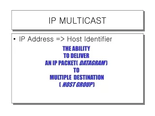
What Is Multicast • Unicast is one to one • traffic is sent from a single source to a single destination • Multicast is one to many • traffic is sent from a single source to a “group” address
Unicast vs. Multicast Unicast Server Router Multicast Server Router
More efficient method of sending the same data to lots of hosts Distributing a video stream to multiple viewers Allows unique distributed protocols clients can announce services or perform queries in a distributed fashion ala Appletalk’s “Chooser” Why Multicast
Multicast Disadvantages Multicast Is UDP Based!!! • Best Effort Delivery: Drops are to be expected. Multicast applications should not expect reliable delivery of data and should be designed accordingly. Reliable Multicast is still an area for much research. Expect to see more developments in this area. • No Congestion Avoidance: Lack of TCP windowing and “slow-start” mechanisms can result in network congestion. If possible, Multicast applications should attempt to detect and avoid congestion conditions. • Duplicates: Some multicast protocol mechanisms (e.g. Asserts, Registers and SPT Transitions) result in the occasional generation of duplicate packets. Multicast applications should be designed to expect occasional duplicate packets. • Out of Order Delivery: Some protocol mechanisms may also result in out of order delivery of packets.
Agenda • What Is Multicast • Multicast Protocols • Multicast Configurations • Troubleshooting • Futures • Useful Links
Multicast Addressing Basics IGMP PIM MSDP MBGP Multicast Protocols
IP Multicast Group Addresses 224.0.0.0–239.255.255.255 Class “D” Address Space High order bits of 1st Octet = “1110” Reserved Link-local Addresses 224.0.0.0–224.0.0.255 Transmitted with TTL = 1 Examples: 224.0.0.1 All systems on this subnet 224.0.0.2 All routers on this subnet 224.0.0.4 DVMRP routers 224.0.0.5 OSPF routers 224.0.0.13 PIMv2 Routers Multicast Addressing
Administratively Scoped Addresses 239.0.0.0–239.255.255.255 Private address space Similar to RFC1918 unicast addresses Not used for global Internet traffic Used to limit “scope” of multicast traffic Same addresses may be in use at different locations for different multicast sessions Examples Site-local scope: 239.253.0.0/16 Organization-local scope: 239.192.0.0/14 Multicast Addressing
Multicast Addressing IP Multicast MAC Address Mapping (FDDI and Ethernet) 32 Bits 28 Bits 1110 239.255.0.1 5 Bits Lost 01-00-5e-7f-00-01 25 Bits 23 Bits 48 Bits
Multicast Addressing IP Multicast MAC Address Mapping (FDDI & Ethernet) Be Aware of the 32:1 Address Overlap 32 - IP Multicast Addresses 224.1.1.1 224.129.1.1 225.1.1.1 225.129.1.1 . . . 238.1.1.1 238.129.1.1 239.1.1.1 239.129.1.1 1 - Multicast MAC Address (FDDI and Ethernet) 0x0100.5E01.0101
Multicast Addressing • Dynamic Group Address Assignment • Historically accomplished using SDR application • Sessions/groups announced over well-known multicast groups • Address collisions detected and resolved at session creation time • Has problems scaling • Future dynamic techniques under consideration • Multicast Address Set-Claim (MASC) • Hierarchical, dynamic address allocation scheme • Extremely complex garbage-collection problem. • Long ways off • MADCAP • Similar to DHCP • Need application and host stack support
Multicast Addressing • Static Group Address Assignment (new) • Temporary method to meet immediate needs • Group range: 233.0.0.0 - 233.255.255.255 • Your AS number is inserted in middle two octets • Remaining low-order octet used for group assignment • Defined in IETF draft • “draft-ietf-mboned-glop-addressing-00.txt”
Multicast Addressing Basics IGMP PIM MSDP MBGP Multicast Protocols
Host-Router Signaling: IGMP • How hosts tell routers about group membership • Routers solicit group membership from directly connected hosts • RFC 1112 specifies version 1 of IGMP Supported on Windows 95 • RFC 2236 specifies version 2 of IGMP Supported on latest service pack for Windows and most UNIX systems • IGMP version 3 is specified in IETF draft draft-ietf-idmr-igmp-v3-03.txt
Host sends IGMP Report to join group 224.1.1.1 H3 H3 Report Host-Router Signaling: IGMP Joining a Group H2 H1
Router sends periodic Queries to 224.0.0.1 224.1.1.1 224.1.1.1 224.1.1.1 H2 H3 H1 X X Suppressed Report Suppressed Query Host-Router Signaling: IGMP Maintaining a Group • One member per group per subnet reports • Other members suppress reports
H3 #1 General Query #2 Host-Router Signaling: IGMP Leaving a Group (IGMPv1) H2 H3 H1 • Host quietly leaves group • Router sends 3 General Queries (60 secs apart) • No IGMP Report for the group is received • Group times out (Worst case delay ~= 3 minutes)
224.1.1.1 H3 Leave to 224.0.0.2 #1 Group Specific Query to 224.1.1.1 #2 Host-Router Signaling: IGMP Leaving a Group (IGMPv2) H2 H3 H1 • Host sends Leave message to 224.0.02 • Router sends Group specific query to 224.1.1.1 • No IGMP Report is received within ~3 seconds • Group 224.1.1.1 times out
draft-ietf-idmr-igmp-v3-??.txt Early implementations now in beta Enables hosts to listen only to a specified subset of the hosts sending to the group IGMPv3
IGMPv3 Source = 1.1.1.1 Group = 224.1.1.1 Source = 2.2.2.2 Group = 224.1.1.1 R2 R1 • H1 wants to receive from S = 1.1.1.1 but not from S = 2.2.2.2 • With IGMP, specific sources can be pruned back - S = 2.2.2.2 in this case R3 IGMPv3: Join 1.1.1.1, 224.1.1.1 Leave 2.2.2.2, 224.1.1.1 H1 - Member of 224.1.1.1
Multicast Addressing Basics IGMP PIM MSDP MBGP Multicast Protocols
Distribution Trees Neighbor Discovery PIM-DM PIM-SM PIM
Multicast Distribution Trees Shortest Path or Source Distribution Tree Source 1 Notation: (S, G) S = Source G = Group Source 2 A B F D C E Receiver 1 Receiver 2
Multicast Distribution Trees Shortest Path or Source Distribution Tree Source 1 Notation: (S, G) S = Source G = Group Source 2 A B F D C E Receiver 1 Receiver 2
Shared Tree Multicast Distribution Trees Shared Distribution Tree Notation: (*, G) * = All Sources G = Group A B F D (RP) (RP) PIM Rendezvous Point C E Receiver 1 Receiver 2
Source 1 Source 2 Source Tree Multicast Distribution Trees Shared Distribution Tree Notation: (*, G) * = All Sources G = Group A B F D (RP) (RP) PIM Rendezvous Point C E Shared Tree Receiver 1 Receiver 2
Multicast Distribution Trees • Source or Shortest Path trees Uses more memory O(S x G) but you get optimal paths from source to all receivers; minimizes delay • Shared trees Uses less memory O(G) but you may get sub-optimal paths from source to all receivers; may introduce extra delay Characteristics of Distribution Trees
PIM Neighbor Discovery • PIMv2 Hellos are periodically multicast to the “All-PIM-Routers” (224.0.0.13) group address. (Default = 30 seconds) • Note: PIMv1 multicasts PIM Query messages to the “All-Routers” (224.0.0.2) group address. • If the “DR” times-out, a new “DR” is elected. • The “DR” is responsible for sending all Joins and Register messages for any receivers or senders on the network. Highest IP Address electedas “DR” (Designated Router) 171.68.37.2 PIM Router 2 PIM Hello PIM Hello PIM Router 1 171.68.37.1
PIM Neighbor Discovery wan-gw8>show ip pim neighbor PIM Neighbor Table Neighbor Address Interface Uptime Expires Mode 171.68.0.70 FastEthernet0 2w1d 00:01:24 Dense 171.68.0.91 FastEthernet0 2w6d 00:01:01 Dense (DR) 171.68.0.82 FastEthernet0 7w0d 00:01:14 Dense 171.68.0.86 FastEthernet0 7w0d 00:01:13 Dense 171.68.0.80 FastEthernet0 7w0d 00:01:02 Dense 171.68.28.70 Serial2.31 22:47:11 00:01:16 Dense 171.68.28.50 Serial2.33 22:47:22 00:01:08 Dense 171.68.27.74 Serial2.36 22:47:07 00:01:21 Dense 171.68.28.170 Serial0.70 1d04h 00:01:06 Dense 171.68.27.2 Serial1.51 1w4d 00:01:25 Dense 171.68.28.110 Serial3.56 1d04h 00:01:20 Dense 171.68.28.58 Serial3.102 12:53:25 00:01:03 Dense
PIM-DM — Evaluation • Most effective for small pilot networks • Advantages: • Easy to configure—two commands • Simple flood and prune mechanism • Potential issues... • Inefficient flood and prune behavior • Complex Assert mechanism • Mixed control and data planes • Results in (S, G) state in every router in the network • Can result in non-deterministic topological behaviors • No support for shared trees
PIM-SM Overview • Explicit join model • Receivers join to the Rendezvous Point (RP) • Senders register with the RP • Data flows down the shared tree and goes only to places that need the data from the sources • Last hop routers can join source tree if the data rate warrants by sending joins to the source • RPF check depends on tree type • For shared trees, uses RP address • For source trees, uses Source address
PIM-SM Overview • Only one RP is chosen for a particular group • RP statically configured or dynamically learned (Auto-RP, PIM v2 candidate RP advertisements) • Data forwarded based on the source state (S, G) if it exists, otherwise use the shared state (*, G) • RFC 2326 - “PIM Sparse Mode Protocol Spec”
(*, G) Join Shared Tree PIM-SM Shared Tree Join RP (*, G) State created only along the Shared Tree. Receiver
Source (S, G) Register (unicast) (S, G) Join Traffic Flow Source Tree PIM-SM Sender Registration RP (S, G) State created only along the Source Tree. Shared Tree Receiver
Source (S, G) Register (unicast) Traffic Flow Source Tree (S, G) Register-Stop (unicast) PIM-SM Sender Registration RP (S, G) traffic begins arriving at the RP via the Source tree. Shared Tree RP sends a Register-Stop back to the first-hop router to stop the Register process. Receiver
Source Traffic Flow Source Tree PIM-SM Sender Registration RP Source traffic flows nativelyalong SPT to RP. From RP, traffic flows downthe Shared Tree to Receivers. Shared Tree Receiver
Source (S, G) Join Traffic Flow Source Tree PIM-SM SPT Switchover RP Last-hop router joins the Source Tree. Shared Tree Additional (S, G) State is created along new part of the Source Tree. Receiver
Source Traffic Flow Source Tree (S, G)RP-bit Prune PIM-SM SPT Switchover RP Traffic begins flowing down the new branch of the Source Tree. Shared Tree Additional (S, G) State is created along along the Shared Tree to prune off (S, G) traffic. Receiver
Source Traffic Flow Source Tree PIM-SM SPT Switchover RP (S, G) Traffic flow is now pruned off of the Shared Tree and is flowing to the Receiver via the Source Tree. Shared Tree Receiver
Source Traffic Flow Source Tree (S, G) Prune PIM-SM SPT Switchover RP (S, G) traffic flow is no longer needed by the RP so it Prunes the flow of (S, G) traffic. Shared Tree Receiver
Source Traffic Flow Source Tree PIM-SM SPT Switchover RP (S, G) Traffic flow is now only flowing to the Receiver via a single branch of the Source Tree. Shared Tree Receiver
PIM-SM Protocol Mechanics • PIM SM State • PIM SM Forwarding • PIM SM Joining • PIM SM Registering • PIM SM SPT-Switchover • PIM SM Pruning
PIM-SM State Example sj-mbone> show ip mroute IP Multicast Routing Table Flags: D - Dense, S - Sparse, C - Connected, L - Local, P - Pruned R - RP-bit set, F - Register flag, T - SPT-bit set, J - Join SPT M - MSDP created entry, X - Proxy Join Timer Running A - Advertised via MSDP Timers: Uptime/Expires Interface state: Interface, Next-Hop or VCD, State/Mode (*, 224.1.1.1), 00:13:28/00:02:59, RP 10.1.5.1, flags: SCJ Incoming interface: Ethernet0, RPF nbr 10.1.2.1, Outgoing interface list: Ethernet1, Forward/Sparse, 00:13:28/00:02:32 Serial0, Forward/Sparse, 00:4:52/00:02:08 (171.68.37.121/32, 224.1.1.1), 00:01:43/00:02:59, flags: CJT Incoming interface: Serial0, RPF nbr 192.10.2.1 Outgoing interface list: Ethernet1, Forward/Sparse, 00:01:43/00:02:11 Ethernet0, forward/Sparse, 00:01:43/00:02:11
PIM-SM (*,G) State Rules • (*,G) creation • Upon receipt of a (*,G) Join or • Automatically if (S,G) must be created • (*,G) reflects default group forwarding • IIF = RPF interface toward RP • OIL = interfaces • that received a (*,G) Join or • with directly connected hosts or • manually configured • (*,G) deletion • When OIL = NULL and • no child (S,G) state exists
PIM-SM (S,G) State Rules • (S,G) creation • By receipt of (S,G) Join or Prune or • By “Register” process • Parent (*,G) created (if doesn’t exist) • (S,G) reflects forwarding of “S” to “G” • IIF = RPF Interface normally toward source • RPF toward RP if “RP-bit” set • OIL = Initially, copy of (*,G) OIL minus IIF • (S,G) deletion • By normal (S,G) entry timeout
PIM-SM OIL Rules • Interfaces in OIL added • By receipt of Join message • Intfc’s added to (*,G) are added to all (S,G)’s • Interfaces in OIL removed • By receipt of Prune message • Intfc’s removed from (*,G) are removed from all (S,G)’s • Interface Expire timer counts down to zero • Timer reset (to 3 min.) by receipt of periodic Join or • By IGMP membership report
PIM-SM State Flags • S = Sparse Mode • C = Directly Connected Host • L = Local (Router is member) • P = Pruned (All intfcs in OIL = Prune) • T = Forwarding via SPT • Indicates at least one packet was forwarded
PIM-SM State Flags (Cont.) • J = Join SPT • In (*, G) entry • Indicates SPT-Threshold is being exceeded • Next (S,G) received will trigger join of SPT • In (S, G) entry • Indicates SPT joined due to SPT-Threshold • If rate < SPT-Threshold, switch back to Shared Tree • F = Register • In (S,G) entry • Indicates the router is a first-hop router and there is a directly connected source or proxy registers are being sent. • In (*, G) entry • Set when “F” set in at least one child (S,G)