Download
1 / 44
440 likes | 554 Views
In this lecture, we will delve into the critical role of interrupts in microprocessor systems, discussing their necessity, sources, and complexity in managing tasks. Interrupt controllers and the associated challenges of interrupt management will be highlighted. We will explore the structure of interrupt vectors in ARM Cortex-M3 and review the operation of the Nested Vectored Interrupt Controller (NVIC). Furthermore, the session will introduce serial buses including UART, I2C, and SPI, laying the groundwork for understanding multi-drop bus architecture.

E N D
EECS 373 Design of Microprocessor-Based Systems Mark Brehob University of Michigan Lecture 7:Finish interrupts, group talks, start on serial buses Feb 4th 2014
Announcements • Recall we have a Monday night group formation meeting from 6:30-8:00pm • Everyone needs to be there. • In 1500 EECS. • Exam will be on Tuesday 2/25 in class. • HW3 will be posted later this week. • Thursday’s lecture will be ~30 minutes of class material and 50 minutes of project discussion.
High-level review of interrupts • Why do we need them? Why are the alternatives unacceptable? • Convince me! • What sources of interrupts are there? • Hardware and software! • What makes them difficult to deal with? • Interrupt controllers are complex: there is a lot to do! • Enable/disable, prioritize, allow premption (nested interrupts), etc. • Software issues are non-trivial • Can’t trash work of task you interrupted • Need to be able to restore state • Shared data issues are a real pain
And the interrupt vectors (in startup_a2fxxxm3.s found in CMSIS, startup_gcc) g_pfnVectors: .word _estack .word Reset_Handler .word NMI_Handler .word HardFault_Handler .word MemManage_Handler .word BusFault_Handler .word UsageFault_Handler .word 0 .word 0 .word 0 .word 0 .word SVC_Handler .word DebugMon_Handler .word 0 .word PendSV_Handler .word SysTick_Handler .word WdogWakeup_IRQHandler .word BrownOut_1_5V_IRQHandler .word BrownOut_3_3V_IRQHandler .............. (they continue)
Pending interrupts The normal case. Once Interrupt request is seen, processor puts it in “pending” state even if hardware drops the request. IPS is cleared by the hardware once we jump to the ISR. This figure and those following are from The Definitive Guide to the ARM Cortex-M3, Section 7.4
In this case, the processor never took the interrupt because we cleared the IPS by hand (via a memory-mapped I/O register)
ARM interrupt summary • We’ve got a bunch of memory-mapped registers that control things (NVIC) • Enable/disable individual interrupts • Set/clear pending • Interrupt priority and preemption • We’ve got to understand how the hardware interrupt lines interact with the NVIC • And how we figure out where to set the PC to point to for a given interrupt source.
2. How external lines interact with the NVIC The normal case. Once Interrupt request is seen, processor puts it in “pending” state even if hardware drops the request. IPS is cleared by the hardware once we jump to the ISR. This figure and those following are from The Definitive Guide to the ARM Cortex-M3, Section 7.4
3. How the hardware figures out what to set the PC to g_pfnVectors: .word _estack .word Reset_Handler .word NMI_Handler .word HardFault_Handler .word MemManage_Handler .word BusFault_Handler .word UsageFault_Handler .word 0 .word 0 .word 0 .word 0 .word SVC_Handler .word DebugMon_Handler .word 0 .word PendSV_Handler .word SysTick_Handler .word WdogWakeup_IRQHandler .word BrownOut_1_5V_IRQHandler .word BrownOut_3_3V_IRQHandler .............. (they continue)
So let’s say a GPIO pin goes high- When will we get an interrupt?- What happens if the interrupt is allowed to proceed?
Example of Complexity: The Reset Interrupt • No power • System is held in RESET as long as VCC15 < 0.8V • In reset: registers forced to default • RC-Osc begins to oscillate • MSS_CCC drives RC-Osc/4 into FCLK • PORESET_N is held low • Once VCC15GOOD, PORESET_N goes high • MSS reads from eNVM address 0x0 and 0x4
Talk about talks • Groups of 2-3 folks • Not your lab partner • 12 minutes for the talk, ~3 minutes for questions • Four parts • Meet with me about 2-3 weeks ahead of time to discuss topic idea. • Give first practice talk about 1-2 weeks before scheduled date (10%) • Second practice talk a few days before scheduled date (10%) • Give talk in class (80%)
Topic talk (continued) • Each talk must include • An explanation of how the topic relates to embedded systems • An understanding of high-level issues including tradeoffs • Need to produce at least one original graph explaining tradeoffs. • Some detailed explanation of a relevant part of the topic • Where others can go to learn more information • We’ll take 10 minutes at the end of class to form groups of 2-3. • By 9pm groups should fill out form at http://tinyurl.com/373TTW14If you don’t have a group by that time, send me an e-mail and I’ll form them.
Start Serial Buses Some generic information (UART, I2C, and SPI next Tuesday)
Fun with buses • A multidrop bus (MDB) is a computer bus in which all components are connected to the same set of electrical wires. (from Wikipedia) • In the general case, a bus may have more than one device capable of driving it. • That is, it may be a “multi-master” bas as discussed earlier.
How can we handle multiple (potential) bus drivers? (1/3) • Tri-state devices, just haveone device drive at a time. Everyone can read though • Pros: • Very common, fairly fast, pin-efficient. • Cons: • Tri-state devices can be slow. • Especially drive-to-tristate? • Need to be sure two folks not driving at the same time • Let out the magic smoke. • Most common solution (at least historically) • Ethernet, PCI, etc.
How can we handle multiple (potential) bus drivers? (2/3) • MUX • Just have each device generate its data, and have a MUX select. • That’s a LOT of pins. • Consider a 32-bit bus with 6 potential drivers. • Draw the figure. • How many pins needed for the MUX? • Not generally realistic for an “on-PCB” design as we’ll need an extra device (or a lot of pins on one device) • But reasonable on-chip • In fact AHB, APB do this.
How can we handle multiple (potential) bus drivers? (3/3) • “pull-up” aka “open collector” aka “wired AND” • Wire is pulled high by a resistor • If any device pulls the wire low, it goes low. • Pros: • If two devices both drive the bus, it still works! • Cons: • Rise-time is very slow. • Constant power drain. • Pros: • If two devices both drive the bus, it still works! • Cons: • Rise-time is very slow. • Constant power drain. • Sees use in I2C, CAN.
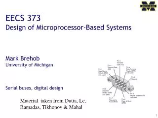
External memory attaches to the processor via the external memory controller and bus Atmel SAM3U