Download
1 / 60
620 likes | 1.18k Views
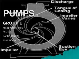
Working principles of pumps. History of Reciprocating pumps. In 17 th century Egyptians in Alexandria built reciprocating fire pump and and it had all the parts of today ’ s pump. About 1805 Newcomen (Great Britain) built a reciprocating pump using steam engine as the driver.

E N D
History of Reciprocating pumps In 17th century Egyptians in Alexandria built reciprocating fire pump and and it had all the parts of today’s pump. About 1805 Newcomen (Great Britain) built a reciprocating pump using steam engine as the driver. He was the first man to use seam for driving purposes. In 1840-50 Worthington (U.S.A) developed a steam engine driven pump. Then many developments came.
History of Centrifugal pumps pumps The inventor ca not be name with assurance. In the 17th century Jordan, an Italian had made some drawing of a centrifugal pumps. In the early 18 century French physicist Papin built a centrifugal pump of primitive design. In 1732 Demouir pumps was put on service in France, In 1818 Andrews ( USA) built a single stage centrifugal pump. Then many developments came in the industry...
History of best pump Human heart. Everybody knows Who invented.
200 meters 100 Bar M 10 kms • Pumps are used to move liquids • from a lower pressure system to higher pressure • From a lower elevation to higher elevation • From one place to another place at different/same elevation and pressure.
200 meters 100 Bar 10 kms M Pumps add pressure energy to over come elevation needs ( potential energy) Frictional losses Delta pressure requirements Energy needed for pumps= volumetric flow*pressure
Power = mass X dynamic head Power ( kW)= H Q r/367000 H = Total head in metersQ=Flow M3/H r=Density in Kg/M3 Power required for pumping Power ( kW)= H Q r/35.99 H = Total head in barAQ= Flow M3/H r=Density in Kg/M3 Pleased divide by efficiency for actual power Please refer Perry
How to give energy ? Centrifugal force (throwing) Positive displacement (physically pushing)
Impeller • Casing • Eye • Seal/packing • Wear ring Parts of a centrifugal pump
It simple and easy to construct. Available in different materials . • Absence of valves. Less maintenance. • High rpm design. Can be coupled to a motor directly. • Steady delivery. • No damage in delivery is blocked. • Smaller in Size when compared to reciprocating type for the same capacity. • Can handle slurries. Advantages of centrifugal pumps
For high pressure we need multistage pump which are complex to construct. • Efficiency is high only over a range.( explain graph) • Usually not self priming • Non return valve is needed in the delivery to avoid back flow. • Very viscous fluid can not be handled/ Dis-Advantages of centrifugal pumps
Types centrifugal pumps • Typical classification • Single stage • Multistage Explain why and how
Multi stage Multistage pumps are used to limit rpm and whenever we have high DP. Example BFW pumps.
Thrust balance centrifugal pumps 1. Double suction pumps 2. Thrust balance in multistage pumps Stage arrangement 3. Thrust balance line and thrust disk and bearing
Double suction pumps Sea water
Multistage pumps Thrust balance in a multi-stage pump
Multistage pumps Out In Thrust balance in a multi-stage pump Explain the principle of balance disc Thrust balance line and caution
Multistage pump Explain thrust balance
Positive displacement pumps • Reciprocating • Rotary
Reciprocating Pumps • Piston type • Vertical& Horizontal & double acting • Plunger type • Diaphragm pump
Reciprocating pumps Explain double acting, plunger type , vertical, horizontal, multistage
Diaphragm Reciprocating pumps Basic principle is similar to a reciprocating plunger pump/ Plunger pressurizes the hydraulic oil which when pressurized pushes the diaphragm and discharge starts. Stroke length can be adjusted and hence the dosing flow rate. No direct contact of plunger with the solution. Direct contact is only with diaphragm ( neoprene, Teflon etc)
Figure 1:The air valve directs pressurized air to the back side of diaphragm "A". The compressed air is applied directly to the liquid column separated by elastomeric diaphragms. The compressed air moves the diaphragm away from the center block of the pump. The opposite diaphragm is pulled in by the shaft connected to the pressurized diaphragm. Diaphragm "B" is now on its air exhaust stroke; air behind the diaphragm has been forced out to atmosphere through the exhaust port of the pump. The movement of diaphragm "B" toward the center block of the pump creates a vacuum within the chamber "B". Atmospheric pressure forces fluid into the inlet manifold forcing the inlet ball off its seat. Liquid is free to move past the inlet valve ball and fill the liquid chamber. Diaphragm Reciprocating pumps
Figure 2: When the pressurized diaphragm, diaphragm"A", reaches the limit of its discharge stroke, the air valve redirects pressurized air to the back side of diaphragm "B". The pressurized air forces diaphragm "B" away from the center block while pulling diaphragm "A" to the center block. Diaphragm "B" forces the inlet valve ball onto its seat due to the hydraulic forces developed. These same hydraulic forces lift the discharge valve ball, forcing fluid flow to flow through the pump discharge. The movement of diaphragm "A" to the center block of the pump creates a vacuum within liquid chamber "A". Atmospheric pressure forces fluid into the inlet manifold of the pump. The inlet valve ball is forced off its seat allowing the fluid being transferred to fill the liquid chamber. Diaphragm Reciprocating pumps
Diaphragm Reciprocating pumps Figure 3: Upon completion of the stroke, the air valve again redirects air to the back side of diaphragm "A", and starts diaphragm "B" on its air exhaust stroke. As the pump reaches its original starting point, each diaphragm has gone through one air exhaust or one fluid discharge stroke. This constitutes one complete pumping cycle. The pump may take several cycles to become completely primed depending on the conditions of the application.
Gear and screw pumps • High pressure and viscous fluids • Used in Samd for lube and seal oil pumps air booster of ammonia, 102-J
Gear pumps • High pressure and viscous fluids • Example : lube/ seal oil pumps
Screw pumps • High pressure and viscous fluids • Example : lube/ seal oil pumps
SCREW PUMP Talk about selection, parallel operation, reverse running etc.
SCREW PUMP Talk about selection, parallel operation, reverse running etc.
SCREW PUMP Talk about selection, parallel operation, reverse running etc.
Sealing in pumps Fixed sealing – Packing Centrifugal and reciprocating Rotating – Mechanical seal Centrifugal, gear pumps etc
Stuffing box Impeller Gland packing principles Explain packing stuffing box , heat generation and cooling techniques. , Lantern rings ,flushing ,Cost and choice etc.
Packing Explain packing stuffing box , heat generation and cooling techniques. , Lantern rings ,flushing ,Cost and choice etc.
Stuffing box 3 2 Impeller 1 Fixed Rotating Three sealing points of a mechanical seal ( 1,2, and 3)