Download
1 / 84
1.27k likes | 2.02k Views
Access Network: Base Station Subsystem. Core Network: GSM CS network. HLR. VLR. EIR. AuC. BSC. BTS. SS7. Mobile Station. MSC. PSTN. BTS. Um Abis A. GSM Network Overview. GSM Network Architecture. MS: Mobile Station BSS: Base Station Subsystem

E N D
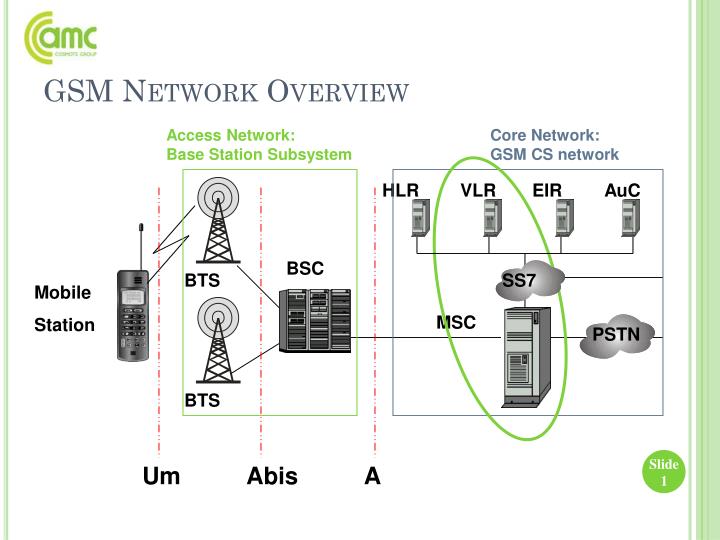
Access Network: Base Station Subsystem Core Network: GSM CS network HLR VLR EIR AuC BSC BTS SS7 Mobile Station MSC PSTN BTS Um Abis A GSM Network Overview
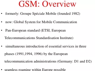
GSM Network Architecture • MS: Mobile Station • BSS: Base Station Subsystem • MSC: Mobile Switching Center • O&M: Operations and Maintenance Center • VLR, HLR, AuC, EiR … • CGSN Prepared by E.Stambolliu, M.Koci & E.Kola
Mobile Station (MS) • Mobile Equipment (ME) • SIM: Subscriber Identity Module • While subscriber roams or is stationary, the MS transmits a radio signal to one of the many BTS using a radio-link protocol via the Um interface
The Base Station System (BSS) • All radio-related functions performed in BSS • The Base Station Controller (BSC) • Is a high-capacity switch • Provides all control functions and physical links between the MSC and the BTS • A group of BSCs is served by an MSC • The Base Transceiver Station (BTS) • Handles the radio interface to the mobile unit • Consists of transceivers and cell antennas • A group of BTSs is controlled by a BSC
BSS (Base Station Subsystem) • BSC handles (through the Abis interface): • Radio-channel setup • Frequency hopping • Handovers • BSC also connects MSto MSC usingA interface
BSS (Base Station Subsystem) • Sometimes a Transcoder Rate Unit (TRAU) is placed on BTS to perform transcoding between 64 KbpsA-law and 13 Kbps RPE/LTP(Regular Pulse Excited Long Term Prediction) speech channels HLR VLR EIR AuC BSC BTS SS7 MSC PSTN BTS Um Abis A TRAU
Mobile Services Switching Center • The MSC performs the telephony switching functions of the network • Controls calls to and from other telephone and data systems • Interface between radio system and fixed networks (PSTN and ISDN) • Connected to BSS through A interface; usually an E-1,either wireline or microwave • Also performs functions such as: • Toll ticketing • Network interfacing • Common channel signaling
MSC (Mobile Switching Center) (2) • Each MSC covers several cells (BSSs)
MSC (Mobile Switching Center) (3) • Also performs signaling between MSC and other functional entities using SS7: • Registration • Authentication • Location updating • Handovers • Call routing to a roaming subscriber
Other GSM Network Entities • HLR: Home Location Register • VLR: Visitor Location Register • EIR: Equipment Identity Register • AuC: Authentication Center
Home Location Register • The HLR is the most important database • Storage and management of subscriptions • Permanent data includes • Subscriber’s service profile • Subscriber’s location information • Subscriber’s activity status • Subscribing to a particular provider’s service registers you in the HLR of that provider
HLR (Home Location Register) • Central database for all subscribers: • Identity of the subscriber • Services accessible to the subscriber • Current location of the subscriber • Given a Mobile Subscriber ISDN number (MS-ISDN), call is routed to IMSI number-VLR • Each subscriber appears only once in database • HLR might be physically distributed in several sites (e.g., using first two digits to identify physical HLR)
Visitor Location Register • The VLR contains temporary data about visiting (roaming) subscribers • It’s always integrated with the MSC • When a roamer enters the service area the VLR queries the appropriate HLR • If a roamer makes a call the VLR will already have the information it needs for call setupDatabase with information on MS within area served by MSC: • MS Roaming number • TMSI if applicable • Location area in which was last registered • Supplementary services • Used by an MSC to retrieve information for various purposes: • Handling of calls to or from a roaming mobile station currently located in its area • Typically part of MSC
AuC (Authentication Center) • Entity associated to HLR for authentication: allow International Mobile Subscriber Identity (IMSI) to be authenticated • Allows ciphering of communication over radio path between mobile station and network ciphered • Transmits data needed for authentication and ciphering via HLR to VLR, MSC and SGSN which need to authenticate a mobile station (SIM validation)
Ki is stored in SIM card and AUC Generate RAND AUC MS RAND+Ki=SRES using A3 AUC MS If the SRES in MS is equal with SRES in AUC the subs is authenticated. RAND+Ki=Kc using A8 AUC MS A3 This is an algorithm used to generate the Signed Response (SRES). A8 This is an algorithm used to generate the CipheringKey (Kc). A3A8 This is an algorithm used to generate Signed Response (SRES) and CipheringKey (Kc). A4 This is an algorithm used for encryption/decryption of Ki.
EIR (Equipment Identity Register) • Logical entity responsible for storing International Mobile Equipment Identities (IMEIs) in network used in GSM system • Equipment classified as "white listed", "grey listed” and "black listed” • Ensures that MEs being used are valid and authorized to function on the Public Land Mobile Network (PLMN)
Operation and Support Center • Operation and Maintenance Center (OMC) • is connected with all the equipment in the switching center and to the BSC • Network operation monitors and controls the system • Provides centralized cost-effective support • Provides a network overview at any moment • Supports maintenance and operational activities for different organizations and groups
Other Functional Elements • Message Center (MXE) – handles voice, fax, and data messaging • Mobile Service Node (MSN) – handles mobile intelligent network (IN) services • Gateway Mobile Services Switching Center (GMSC) – an MSC with a gateway that interconnects two networks • GSM Interworking Unit (GIWU) – hardware and software that enables both voice and data
GSM Specifications • Combination of FDMA and TDMA to send information • Frequencies: 800, 900, 1800, 1900 MHzFor example, GSM 900: • Uplink = 890-915 MHz • Downlink = 935-960 MHz • Each 25 MHz bandwidth is divided into 124 carrier frequencies spaced 200 KHz with one or more frequencies allocated to each base station • Transmission rate: 270 kbps over the air • Speech coder: Linear Predictive Coding (LPC) at 13 kbps – filter reduces the bit rate
GSM Specifications • Frequency range: 1,850 to 1,990 MHz • Duplex distance: 80 MHz • Channel separation: 200 kHz • Modulation: Gaussian minimum shift keying • Transmission rate: 270 kbps over the air • Access method: Time Division Multiple Access • Speech coder: Linear Predictive Coding (LPC) at 13 kbps – filter reduces the bit rate
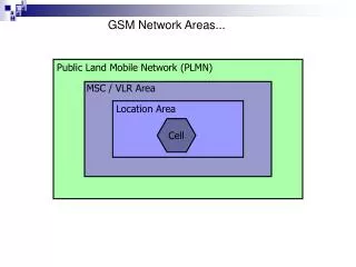
GSM Network Areas • In order of increasing geographic size: • Cell – the area covered by one BTS – a number of these make up a: • Location Area (LA) – a group of cells – a group of LAs makes up an: • MSC/VLR service area – area covered by one MSC – a number of these make up the: • Public Land Mobile Network (PLMN) service area– one operator’s network
CGI- Cell Global Identification MCC-MNC-LAC-CI where: MCC Mobile country code MNC Mobile network code LAC Location area code CI Cell identity
BaseStation Identity Code Expressed as nccbcc where: ncc PLMN colour code bccBScolour code
Handover • Four types of handovers: • Channels (time slots) in same cell • Between cells within same BSC • Between BSCs, within same MSC • Between MSCs
Addressing of managed objects MO MO class MO type Addressing Limit TG Transceiver Group RXOTG 0 <= tg <= 511 CF Central Function RXOCF 0 <= tg <= 511 TF Timing Function RXOTF 0 <= tg <= 511 IS Interworking Switch RXOIS 0 <= tg <= 511 DP Digital Path RXODP 0 <= dp <= 1 TRXC Transceiver Controller RXOTRX 0 <= trxc <= 15 RX Receiver RXORX 0 <= trxc <= 15 TX Transmitter RXOTX 0 <= trxc <= 15 TS Time Slot RXOTS 0 <= ts <= 7
DXU - Distribution Switch Unit functions • CF • Central Function, is the control part of a TG. It is a SW function, handling common control functions within a TG. • The BSC communicates with the CF using layer 2 LAPD, and is • addressed by its TEI = 62. • CON • LAPD Concentrator, is used by the optional feature LAPD Concentration for RBS 2000. It is connected to DCP 64&&87. • IS • Interworking Switch, provides a system interface to the 2 Mbit/s link and cross connects individual time slots to certain transceivers. • TF • Timing Function, extracts synchronization information from the PCM link and generates a timing reference for the RBS. • DP • Digital Path, Layer 1 reception and transmission are not part of the BTS logical model. However, each of the PCM systems terminating in TG has an associated supervision object, the DP.
TRU - Transceiver Unit functions • TRXC The transceiver controller is controlling all the functions for Signal processing, Radio receiving and Radio Transmitting. • Each TRX corresponds to one TRU unit. • The BSC currently supports a maximum of 1020 TRXs. • RX The receiver is an application object. It provides the radio frequency reception functionality for one transceiver. • TX The transmitter is an application object. It provides the radio frequency transmission functionality on a time slot basis for eight TSs using different time slot numbers.