Download
1 / 1
20 likes | 301 Views
Analyzing the Forces W ithin U nilateral T ranstibial P rosthetic S ockets and Design of an Improved F orce M inimizing S ocket. Transtibial Amputees Over 40,000 transtibial (below the knee) amputations are performed annually in United States [4].

E N D
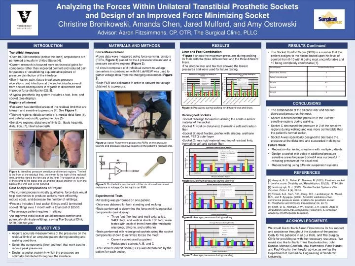
Analyzing the Forces Within Unilateral TranstibialProsthetic Sockets and Design of an Improved Force Minimizing Socket Transtibial Amputees Over 40,000 transtibial (below the knee) amputations are performed annually in United States [4]. Current research is focused more on financial gains for companies rather than improved comfort and reduced pain for patients or establishing a quantitative picture of pressure distribution of the interface. Skin irritation, pain, tissue breakdown, pressure ulcerations, and infections at the socket interface result from socket inadequacies in regards to discomfort and improper force distribution [2],[3]. A typical prosthetic leg system includes a foot, liner, and socket (see display). Regions of Interest Research has identified areas of the residual limb that are tolerant and sensitive to pressure [4]. See Figure 1. Tolerant regions: tibialis anterior (1), medial tibial flare (3), mid patella tendon (4), gastrocnemius (5) Sensitive regions: distal end of limb (2), fibula head (6), distal tibia (7), tibial tubercle(8) Figure 1: Identified pressure sensitive and tolerant regions. The left is the front of the residual limb, the center is the right of the residual limb, and the right is the left side of the limb. The region at the end of the stump is the distal end (2) and the tibialis anterior (1) is on the back of the limb and is not pictured. Cost Analysis/Implications of Project The current process is mostly qualitative, force data would help prosthetists to produce sockets more efficiently, reduce costs, and decrease the number of refittings. Process includes 3 test socket fittings and 2 laminated socket fittings over 1 month with a total cost of $2500. The average patient requires 1 refitting. An improved initial socket would increase comfort and potentially eliminate refittings, saving The Surgical Clinic $180,000 per year. INTRODUCTION OBJECTIVES Force Measurement Force data were measured using force-sensing resistors (FSRs, Figure 3) placed on the 4 pressure tolerant and 4 pressure sensitive regions (Figure 2). A circuit composed of 8 individual current-to-voltage converters in combination with NI LabVIEW was used to gather voltage data from the changing resistances (Figure 3). Each FSR was calibrated in order to convert the voltage obtained to a pressure. Figure 2: Aaron Fitzsmmons places the FSRs on the pressure tolerant and pressure sensitive regions of the patient’s residual limb. Figure 3:On the left is a schematic of the circuit used to convert resistance to voltage. On the right is an FSR. Experimental Tests All testing was performed on one patient. Data was obtained for both standing and walking. Tests performed to determine the force minimizing socket components (see display): • Three feet (flex-foot and multi-axial ankle, SACH foot, and vertical shank ESF foot) were tested with each of three liners (thermoplastic elastomer, silicone, and urethane) Tests performed with redesigned sockets using the socket components shown to minimize forces the most: • Current socket used by patient • Redesigned sockets A, B, and C The Socket Comfort Score (SCS) was determined by the patient for each socket. MATERIALS AND METHODS Liner and Foot Combination Figure 4 shows the maximum pressures during walking for trials with the three different feet and the three different liners. The silicone liner and flex foot showed the lowest pressures and were used for future testing. Figure 4: Pressures during walking for different feet and liners. Redesigned Sockets Socket redesign focused on altering the contour and/or material of the socket. Socket A: void on distal end, thermaline soft and carbon fiber Socket B: most flexible, proflex with silicone, urethane insert, PETG outer layer Socket C: less rigid material near top of residual limb, thermaline soft and carbon fiber Figure 5: Maximum pressures during walking Figure 6: Average pressures during walking Figure 7: Average pressures during standing RESULTS RESULTS Continued The Socket Comfort Score (SCS) is a number that the patient assigns to the socket based upon his level of comfort from 0-10 with 0 being most uncomfortable and 10 being completely comfortable[1]. The combination of the silicone liner and flex foot decreased pressures the most. Socket B decreased the pressure in the 3 of the sensitive regions during walking. Socket C decreased the pressure in 2 of the sensitive regions during walking and was more comfortable than the patient’s normal socket. Socket A was specifically designed to decrease the pressure at the distal end and succeeded in doing so. Future Work Repeat similar testing situations with multiple patients. Design a socket with voids in additional pressure sensitive areas because Socket A was successful in reducing pressure at the distal end. Repeat testing using different suspension systems REFERENCES [1] Hanspal, R. S., Fisher, K., Nieveen, R. (2003). Prosthetic socket fit comfort score. Disability and Rehabilitation, 25 (22), 1278-1280. [2] Jendrzejczyk, D. J. (1985). Flexible Socket Systems. Clin. Prosthet. Orthot. 9 (4), 27-31. [3] Polliack, A.A., Sieh, R.C., Craig, D.D., Landsberger, S., Mcneil, D.R., and E. Ayyappa. (2000). Scientific validation of two commercial pressure sensor systems for prosthetic socket fit. Prosthetics and Orthotics International, 24, 63-73. [4] Smith, D. G., Michael, J. W., Bowker, J. H. (2004). Atlas of Amputations and Limb Deficiencies. Rosemont, IL: American Academy of Orthopaedic Surgeons. ACKNOWLEDGMENTS We would like to thank Aaron Fitzsimmons for his support and assistance throughout the duration of the project, Cody for his patience in all our trials, and The Surgical Clinic for providing us with the necessary resources. We would also like to thank Franz Baudenbacher, John Dunbar, Michael Goldfarb, Max Hammond, Rene Harder, and Paul King for their helpful advice, as well as the Department of Biomedical Engineering at Vanderbilt University. Acquire accurate measurements of the pressures on the residual limb of an amputee patient during standing and walking conditions. Select the components (liner and foot) that work best to reduce peak pressures. Design a socket system in which the pressures are optimally distributed throughout the interface. Advisor: Aaron Fitzsimmons, CP, OTR, The Surgical Clinic, PLLC Christine Bronikowski, Amanda Chen, Jared Mulford, and Amy Ostrowski CONCLUSIONS