Download
1 / 54
540 likes | 647 Views
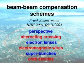
progress of beam-beam compensation schemes. Frank Zimmermann. Thanks to Kazunori Akai, Gerard Burtin, Jackie Camas, Fritz Caspers, Ulrich Dorda, Wolfram Fischer, Jean-Pierre Koutchouk, Kazuhito Ohmi, Yannis Papaphilippou, Francesco Ruggiero,

E N D
progress of beam-beam compensation schemes Frank Zimmermann Thanks to Kazunori Akai, Gerard Burtin, Jackie Camas, Fritz Caspers, Ulrich Dorda, Wolfram Fischer, Jean-Pierre Koutchouk, Kazuhito Ohmi, Yannis Papaphilippou, Francesco Ruggiero, Tanaji Sen, Vladimir Shiltsev, Jorg Wenninger,…
(1) need for beam-beam compensation • nominal LHC parameters are challenging & “at the edge”: • ~20% geometric luminosity loss from crossing angle • chaotic particle trajectories at 4-6s due to long-range beam-beam effects • if we increase #bunches or bunch charge, or reduce b*: • long-range beam-beam effects require larger crossing angle • but geometric luminosity loss would be inacceptable!
Piwinski angle luminosity reduction factor nominalLHC
Impact of crossing angle? Lepton colliders: Strong-strong beam-beam simulations predict an increase in the KEKBbeam-beam tune shift limit by a factor 2-3 for head-on collision compared with the present crossing angle. This is the primary motivation for installing crab cavities. The simulations correctly predict the present performance. [K. Ohmi] Hadron Colliders:RHIC operates with crossing angles of +/- 0.5 mrad due to limited BPM resolution and diurnal orbit motion. Performance of proton stores is very irreproducible and frequently occurring lifetime problems could be related to the crossing angle, but this is not definitely proven. [W. Fischer] Tevatron controls crossing angle to better than 10 mrad, and for angles of 10-20 mrad no lifetime degradation is seen. [V. Shiltsev]
Experiment at SPS Collider K. Cornelis, W. Herr, M. Meddahi, “Proton Antiproton Collisions at a Finite Crossing Angle in the SPS”, PAC91 San Francisco Q~0.45 qc=500 mrad Q>0.7 qc=600 mrad small emittance
to boost LHC performance further various approaches have been proposed: increase crossing angle AND reduce bunch length (higher-frequency rf & reduced longitudinal emittance) [J. Gareyte; J. Tuckmantel, HHH-20004] 2) reduce crossing angle & apply “wire” compensation [J.-P. Koutchouk] 3) crab cavities → large crossing angles w/o luminosity loss [R. Palmer, 1988; K.~Oide, K. Yokoya, 1989; KEKB 2006] 4) collide long intense bunches with large crossing angle [F. Ruggiero, F. Zimmermann, ~2002]
baseline upgrade parameters invoke shorter or longer bunches F. Ruggiero, F. Zimmermann, HHH-2004 beam-beam compensation with wires or crab cavities would change the optimum beam parameters and could greatly affect the IR layout
minimum crossing angle from LR b-b “Irwin scaling” coefficient from simulation note: there is a threshold - a few LR encounters may have no effect! (2nd PRST-AB article with Yannis Papaphilippou) minimum crossing angle with wire compensator need dynamic aperture of 5-6 s & wire compensation not efficient within 2 s from the beam center independent of beam current
(2) wire compensation “BBLR” • SPS studies • simulations • LHC situation • RHIC experiment • US LARP • pulsed wire
SPS experiment: 1 wire models LHC long-range interaction extrapolation to LHC beam- beam distance, ~9.5s, would predict 6 minutes lifetime
SPS experiment: two wires model beam-beam compensation Qx=0.31 beam lifetime no wire 2 wires 1 wire vertical tune lifetime is recovered over a large tune range, except for Qy<0.285
New Simulation Tool: BBTrack Purpose of the code:Weak-strong simulations of long-range and head-on beam-beam interactions and wire compensation. Author: Ulrich Dorda, CERN Programming language: FORTRAN90 Homepage :http://ab-abp-bbtrack.web.cern.ch/ab-abp-bbtrack/ Other codes, used in the past: WSDIFF (F. Zimmermann, CERN) http://care-hhh.web.cern.ch/CARE-HHH/Simulation Codes/Beam-Beam/wsdiff.htm BBSIM (T. Sen, FNAL) http://waldo.fnal.gov/~tsen/BBCODE/public
simulated stability region in x-y plane with1 & 2 SPS wires 19mm (8s) y unstable stable x un- stable stable -19mm (8s) 19mm (8s) -19mm (8s) -19mm 19mm two wires one wire Yellow: stable with two wires & unstable with one Green: unstable with one wire & stable with two U. Dorda
simulation of wire compensation for the SPS experiment unstable stable different initial betatron phases one wire 1 sigma unstable stable two wires U. Dorda 8 sigma 3 sigma 0
unstable particles jump between phase-space ellipses when they approach the wire (or, in LHC, the other beam) x’ x U. Dorda
sensitivity to 2nd wire’s • transverse position: • SPS data • BBSIM simulation • [T. Sen] • BBtrack simulation • [U. Dorda]
Long-Range Beam-Beam Compensation for the LHC • To correct all non-linear effects correction must be local. • Layout: 41 m upstream of D2, both sides of IP1/IP5 current-carrying wires Phase difference between BBLRC & average LR collision is 2.6o (Jean-Pierre Koutchouk)
simulated LHC tune footprint with & w/o wire correction • .16s • .005s • .016s Beam separation at IP MAD (Jean-Pierre Koutchouk, LHC Project Note 223, 2000)
for future wire beam-beam compensators - “BBLRs” -, 3-m long sections have been reserved in LHC at 104.93 m (center position) on either side of IP1 & IP5
LR collisions at IP1 & 5 for nominal bunch LR collisions at IP1 & 5 for extreme PACMAN bunch long-range collisions only without BBLR compensation U. Dorda BBTrack tune footprints for starting amplitudes up to 6s in x and y
LR collisions at IP1 & 5 LR collisions & BBLR at IP1 & 5 nominal bunch compensated long-range collisions only with & without compensation U. Dorda BBTrack tune footprints for starting amplitudes up to 6s in x and y
LR collisions at IP1 & 5 LR collisions & BBLR at IP1 & 5 extreme PACMAN bunch overcompensated long-range collisions only with & without compensation U. Dorda BBTrack tune footprints for starting amplitudes up to 6s in x and y
head-on & LR collisions in IP1 & 5 head-on, LR & BBLR nominal bunch LR compensated 4,10 -1,1 long-range & head-on collisions @ IP1& 5 with & without compensation U. Dorda BBTrack tune footprints for starting amplitudes up to 6s in x and y
PACMAN bunch head-on, LR & BBLR head-on & LR collisions in IP1 & 5 LR over- compensated long-range & head-on collisions @ IP1& 5 with & without compensation U. Dorda BBTrack tune footprints for starting amplitudes up to 6s in x and y
LHC tune scan for nominal bunch, 45 deg. in x-y-plane red: unstable (strong diffusion),blue: stable 0 U. Dorda, BBTrack long-range & head-on 10s stability of nominal bunch improves for almost all tunes 0 long-range & head-on & wire compensation 0.3 0.8 10s Qy
LHC tune scan for PACMAN bunch, 45o in x-y-plane red: unstable (strong diffusion),blue: stable 0 U. Dorda, BBTrack long-range & head-on 10s stability of extreme PACMAN bunch decreases for almost all tunes 0 long-range & head-on & wire compensation 0.3 0.8 10s Qy
tune scan for nominal bunch wire compensation LHC without wire wire increases dynamic aperture by ~2s U. Dorda, BBTrack
tune scan for PACMAN bunch without wire LHC wire “over-” compensation dc wire reduces dynamic aperture by ~2s U. Dorda, BBTrack
6-D effects? - nominal LHC optics: IP5 IP5 up to 1 m vertical disper- sion in the triplet position of BBLR position of BBLR position of BBLR position of BBLR IP1 IP1 position of BBLR position of BBLR
chromaticity from LRBB & wires B. Erdelyi & T. Sen, 2002 d: beam-beam or beam-wire distance in s D: dispersion h: dispersion in s nLR: number of LR encounters e.g., d=9.5, nLR=30, D=0.6 m, b=3000 m → Q’~0.25 chromaticity from long-range collisions or wire is a small effect
Long-Range BB Experiment in RHIC, 28 April 2005, Wolfram Fischer, et al.,1 Bunch per Ring Beam lifetime vs transverse separation - Initial test to evaluate the effect in RHIC. collision at main IP 10 min. lifetime collision at s=10.65m (1) Experiment shows a measurable effect.(2) The beam loss is very sensitive to working point.
Long-Range BB Experiment in RHIC, 28 April 2005, Wolfram Fischer et al., 1 Bunch per Ring … more data sets collision at s=10.65m Some time stamps have to be adjusted (used time of orbit measurement, not orbit change); parameters other than the orbit were changed - not shown. Scan 4 is the most relevant one. collision at s=10.65m
puzzling: BBTrack simulation for RHIC with a single long-range collision predicts no effect, consistent with earlier studies for the LHC
US LHC Accelerator Research Program Task Sheet Task Name: Wire compensation of beam-beam interactions Date: 23 May 2005 Responsible person (overall lead, lead at other labs): Tanaji Sen (FNAL, lead), Wolfram Fischer (BNL) Statement of work for FY06: Statement of work for FY07: CERN Contacts J.P. Koutchouk, F. Zimmermann • Design and construct a wire compensator (either at BNL or FNAL) • Install wire compensator on a movable stand in one of the RHIC rings • Theoretical studies (analysis and simulations) to test the compensation and robustness • Beam studies in RHIC with 1 bunch / beam at flat top & 1 parasitic interaction. • Observations of lifetimes, losses, emittances, tunes, orbits for each b-b separation. • Beam studies to test tolerances on: beam-wire separation w.r.t. b-b separation, wire current accuracy, current ripple • Beam studies with elliptical beams at the parasitic interaction, aspect ratio close to that of the beams in the LHC IR quadrupoles • Compensation of multiple bunches in RHIC with pulsed wire current. Requires additional voltage modulator
not to degrade lifetime for the PACMAN bunches, the wire should be pulsed train by train LHC bunch filling pattern example excitation patterns (zoom)
specifications for pulsed wire compensator 88.9 ms+/-0.0002 ms 23.5 ms+/-0.02 ms (variation with beam energy is indicated) high repetition rate & turn-to-turn stability tolerance
approaches towards solution: • earlier design for pulsed LHC orbit correction by Corlett & Lambertson (LBNL) [was expensive 10 years ago] • fast kicker developments for ILC (KEK, UK) • fast switching devices for induction rf (KEK) • contacts with industry • collaboration with US LARP • advice by Fritz Caspers and other CERN colleagues • start paper study [Ulrich Dorda] • if promising solution is found, possibly lab test • test in RHIC (2007?)
merits of wire compensation • long-range compensation was demonstrated • in SPS using 2 wires (lifetime recovery) • simulations predict 1-2s gain in dynamic • aperture for nominal LHC • allows keeping the same – or smaller – • crossing angle for higher beam current • →no geometric luminosity loss • challenges & plans • further SPS experiments (3rd wire in 2007) • demonstrate effectiveness of compensation • with real colliding beams (at RHIC) • study options for a pulsed wire
Super-KEKB crab cavity scheme 2 crab cavities / beam / IP Palmer for LC, 1988 Oide & Yokoya for storage rings, 1989 first crab cavities will be installed at KEKB in early 2006
history of s.c. crab cavity developments • CERN/Karlsruhe sc deflecting cavity for separating the kaon beam, 1970’s, 2.86 GHz* • Cornell 1.5 GHz crab cavity 1/3 scale models 1991* • KEK 500 MHz crab cavity with extreme polarization, 1993-present, for 1-2 A current, 5-7 mm bunch length • FNAL CKM deflecting cavity, 2000-present* • KEK 2003 new crab cavity design for Super-KEKB, 10 A beam current, 3 mm bunch length, more heavily damped (coaxial & waveguide) • Daresbury is studying crab cavities for ILC, 2005 • Cornell is interested in developing crab cavities for Super-LHC *H. Padamsee, Daresbury Crab Cavity Meeting, April 2004
bunch shortening rf voltage: unfavorable scaling as 4th power of crossing angle and inverse 4th power of IP beam size; can be decreased by reducing the longitudinal emittance; inversely proportional to rf frequency crab cavity rf voltage: proportional to crossing angle & independent of IP beam size; scales with 1/R12; also inversely proportional to rf frequency
R12 & R22(R11) from MAD nominal LHC optics |R12,34|~30-45 m |R22,44|~1 (from crab cavity to IP)
K. Ohmi, HHH-2004 ~1.5 MV@500 MHz KEKB crab cavity • Squashed cell operating in TM2-1-0 (x-y-z) • Coaxial coupler is used as a beam pipe • Designed for B-factories (1〜2A) ~1.5 m Courtesy K. Akai
longitudinal space & crab frequency longitudinal space required for crab cavities scales roughly linearly with crab voltage; desired crab voltage depends on rf frequency); achievable peak field also depends on rf frequency; 2 MV ~ 1.5 m, 20 MV ~ 15 m frequency must be compatible with bunch spacing; wavelength must be large compared with bunch length; 1.2 GHz probably too high; 400 MHz reasonable; 800 MHz perhaps ok
noise • amplitude noise introduces small crossing angle; e.g., 1% jitter → 1%qc/2 cross. angle – tolerance ~0.1% jitter from emittance growth • phase noise causes beam-beam offset; tolerance on LHC IP offset random variation Dxmax~10 nm → tight tolerance on left-right crab phase and on crab-main-rf phase differences Df <0.012o (Dt<0.08 ps) at qc=1 mrad & 400 MHz Df <0.04o (Dt<0.28 ps) at qc=0.3 mrad & 400 MHz