Download
1 / 11
110 likes | 213 Views
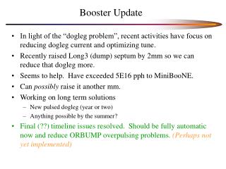
Booster Dampers Update. Nathan Eddy PIP Meeting 4/30/14. Transverse Damper. RF Lock – No loss of lock since “fix” New Firmware with Timofey Zolkin’s n-turn filter coefficients installed Testing and verification underway Basic Timing, Filter Algorithm, Tune Monitor. Longitudinal Damper.

E N D
Booster Dampers Update Nathan Eddy PIP Meeting 4/30/14
Transverse Damper • RF Lock – No loss of lock since “fix” • New Firmware with TimofeyZolkin’s n-turn filter coefficients installed • Testing and verification underway • Basic Timing, Filter Algorithm, Tune Monitor
LD Block Diagram NCO cos NCO cos CIC Dec BP FIR -45° Mɸ CIC Interp 4*RF ~211MS/s 4*RF ~211MS/s x x + ADC DAC Σ ~25KHz + - CIC Dec BP FIR +45° Mɸ CIC Interp x x NCO sin NCO sin Same NCO generates sin, cos for I,Q mixing NCO frequency is centered on rev harmonic of interest Set CIC decimation so that notches on RevF BP FIR is a N tap filter for signal conditioning Mɸ correspond to programmable magnitude/phase shift For output sum, +/- select upper/lower sideband (SSB) Will also suppress carrier Note, this same firmware design can be used for “direct sideband” detection by adjusting the NCO frequency and modifying the FIR filter coefficients
Test Installation Notch Filter RF Ref TCLK BP Filter Mode N Pickup Digital Damper RF Ref WCM Phase Pickup Mode 1
RAW Data 15ms MODE 50
RAW Data Zoom After 90MHz LP Filter
Summary NCO cos NCO cos CIC Dec BP FIR -45° Mɸ CIC Interp 4*RF ~211MS/s 4*RF ~211MS/s x x + ADC DAC Σ ~25KHz + - CIC Dec BP FIR +45° Mɸ CIC Interp x x NCO sin NCO sin ADC through CICdec implemented and tested in Booster CICint and DAC tested on bench Design as shown under checkout right now Expect to begin testing in Booster this week To Do List Develop complete Matlab Simulation Allow ability to optimize filtering Implement Beam Transfer Function Measurement for open and closed loop measurements Straightforward method to optimize gain/phase Demonstrate damping on single Booster Mode