Download
1 / 47
470 likes | 667 Views
Detection of Heart ischemia incl. Detection of heart ischemia using bioimpedance measurement Andres Kink 2012. C ONTENTS C ARDIOVASCULAR SYSTEM M YOCARDIAL ISCHEMIA A NATOMY OF THE HEART C ARDIOVASCULAR SUSTEM AND CORONARY CIRCULATION.

E N D
Detection of Heart ischemia incl. Detection of heart ischemia using bioimpedance measurement Andres Kink 2012
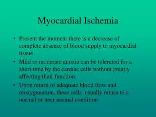
CONTENTS CARDIOVASCULAR SYSTEM MYOCARDIAL ISCHEMIA ANATOMY OF THE HEART CARDIOVASCULAR SUSTEM AND CORONARY CIRCULATION
CARDIOVASCULAR SYSTEM, and CORONARY CIRCULATION Bradycardia or “low heart rate”
CARDIOVASCULAR SYSTEM, and CORONARY CIRCULATION Artifical heart assisting devices
Modern era of implantable pacemakers • The first implantable pacemaker was made by Swedish inventor Dr. Rune Elmqvist, and implanted in 1958 by Dr. Ake Senning. • The first demand pacemaker was introduced by Berkovits in June 1964. Demand pacemakers have additional sensing unit. The aims were - to avoid competition with heart’s own pacemaker (sinus node), and - to save battery energy.
Rate adaptive pacing Heart rate is regulated to maintain body energetic needs. • In the first generation pacemakers the target was reduction of night time heart rate • In the pacemakers of the new generation optimal heart rate calculation is an aim. A multisensor sensing is used (accelometer, ECG, temperature, bioimpedance based, …)
Why Rate Response? Rate response is an ability of a pacemaker to increase the pacing rate in response to physical activity or metabolic demand. Rate response mimics the healthy heart. Special sensor(s) used to determine physical activity are • accelerometer • piezoelectric crystal • minute ventilation (transthoracic impedance) • blood temperature • etc. (e.g., O2) Also combinations of these can be used.
Sensory systems • ECG based interval measurements • Movement analysis (acceleration, ..) • Temperature measurement • Impedance based • Lung impedance • Intraventricular impedance, mostly right ventricle • Myocardial impedance
Problem How to control the pacing rate avoiding imbalance between energy consumption and energy supply of the myocardium, estimating: minute volume (MV) of ventilation relative stroke volume (SV) diastolic time (tdiast) AVOID ISCEMIA, NOT TO MEASURE IT !
Chronotropic Incompetence If the patient’s heart cannot increase its rate appropriately in response to increased activity, the patient is chronotropically incompetent Chronotropic incompetence (definitions): • Maximum heart rate < 90% x (220 - Age) • Maximum heart rate < 120 bpm Causes • aging • drugs • heart disease
Sensors Rate-responsive pacemakers rely on sensor(s) to detect patient activity The ideal sensor should be • Physiologic • Quick to respond • Able to increase the rate proportionally to the patient’s need • Able to work compatibly with the rest of the pacemaker • Able to work well with minimum energy demands or current drain • Easy to program and adjust
Types of Sensors • Activity sensors • Vibration sensors (piezoelectric sensors) • Accelerometers • Physiologic sensors • Minute ventilation • Temperature • Evoked response • QT interval • Closed loop system (CLS) • Virtual sensors
Activity Sensor/Vibration • Responds rapidly • No special pacing leads required • Easy to manufacture and program • Can be “fooled” by pressure on the can or footfalls (like walking downstairs)
Activity/ Accelerometer • Responds rapidly • No special pacing leads required • Easy to manufacture and program • Cannot be “fooled” by pressure on the can
Minute Ventilation • Uses low-level electrical signals to measure resistance across the chest (“transthoracic impedance”) • Requires no special sensor • Requires bipolar pacing leads • Metabolic
Temperature • A thermistor is mounted in the lead (not the can) • Requires a special pacing lead • Metabolic • Response time can be slow
Evoked Response Measures the QRS depolarization area Theory: the QRS depolarization decreases in area with exercise • Requires no special leads • May be affected by changes in posture • Only works when the device is pacing
QT Interval Measures the interval between the pacing spike and the evoked T-wave. Theory: This interval shortens with exercise • Requires no special pacing lead • Works only when the device is pacing
Rate-Responsive Parameters to Program • Base rate • Maximum tracking rate (in DDDR devices) • Maximum sensor rate • Threshold • Slope • Reaction time • Recovery time
Threshold Threshold is the amount of activity needed to cause sensor activity. Can also be set to AUTO: • Measures variations in the last 18 hours of activity • Adjusts threshold automatically • Displays Measured Average Sensor value when pacemaker is interrogated • Offset values can be programmed for more fine-tuning
Threshold Programming Considerations • AUTO allows the pacemaker to automatically adjust to the patient’s changing activity levels • Updates every 18 hours • AUTO with Offset can further fine-tune the settings • A negative value makes it more sensitive (less activity is needed to start rate response) • A positive value makes it less sensitive (more activity is needed to start rate response) • Considerations • Patient age, lifestyle, everyday activities • Patient’s fitness level (how likely is he to go jogging?) • How well patient tolerates higher-rate pacing
Slope Slope describes the sensor-drive pacing rate for a given level of activity. AutoSlope - based on recent activity levels. Threshold in Action
Slope Programming Considerations Slope determines “how much” rate response is given for a specific activity Slope factors are: • The patient’s age, activities, lifestyle • How well he can tolerate rapidly paced activity • How much rate response he needs Slope in Action
Reaction Time in Action Reaction Time When the sensor determines the patient needs in rate response, the Reaction Time parameter regulates how quickly rate response is delivered. Consider the patient’s age, lifestyle, activities, and how quickly he would need rate response • Athletic patients probably need a faster reaction time than couch potatoes • Younger, fitter patients probably need a faster reaction time than older, sedentary patients Programmable to: - Fast, - Medium, - Slow
Recovery Time • Recovery time determines the minimum time it will take the sensor-driven rate at the maximum sensor rate to go back down to the programmed based rate • Similar to Reaction Time • Programmable as Fast, Medium, Slow, and Very Slow • Programming considerations are the usual: • Patient age, lifestyle, activity levels • Tolerance of rate transitions (can he tolerate a rapid change in rate?)
Maximum Sensor Rate • Maximum Sensor Rate is the fastest possible rate the pacemaker will pace in response to sensor input • It does not have to be the same setting as Maximum Tracking Rate (fastest rate the pacemaker will pace the ventricle in response to sensed atrial activity) • The Maximum Sensor Rate must be a rate that the patient can tolerate • Maximum heart rate formula (220-age) x .90 is highest possible setting • But if patient cannot tolerate the maximum heart rate, set the Maximum Sensor Rate to a rate he can tolerate
Threshold • Threshold defines how much activity must occur before the sensor “sees” activity • Most patients do well with AUTO • If AUTO needs some further adjustment, use the offset feature • If sensor seems to react too often or too quickly, program a positive offset • If sensor does not seem to react soon enough or at all, program a negative offset
Reaction and Recovery Times • Reaction time determines how fast rate response goes to work • If the patient does not tolerate abrupt changes in rate, program this to SLOW • Recovery time determines how quickly a sensor-driven rate goes back to the base rate • MEDIUM is a good setting for most patients • SLOW can expose the patient to prolonged periods of pacing at a higher-than-necessary rate
Slope • Slope is “how much” rate response a patient receives once the sensor determines rate response is needed • AUTO is a good middle-of-the-road choice
Possible gates for heart rate control • No gates, fixed heart rate • Heart rate (slope control) • Ventricular volume, minimal stroke volume to maintain body needs • Energy based control : ratio of PVA to myocardial perfusion index during cardiac cycle
Min-max rate gates Allows to act as supervisory system for other cont. algorithms Possibility to increase patient cardiovascular system adaptation Optimal v. min-max rate control • Optimal heart rate • Mostly technical, not from real heart physiology • Underestimates heart rate variability importance
Simplified Calculations oxygen uptake (arterio-venous difference) energetical coefficient myocardial blood volume (balance) hydraulic coronary resistance (energy balance)
Simplified Calculations (cont.) coronary resistance ratio coronary reserve healthy heart arteriosclerosis the condition for myocardium’s energy balance
Volume Measurement - Theory • Gmeas = Gblood + Gp • Gp is parallel conductance of muscle and must be removed to estimate volume • Hypertonic saline bolus injection • Conductance signal increases • Gb-ED & Gb-ES both increase • Conductivity of blood changes but not the conductivity of the muscle
“ISHEMIA” data processing Ischemic damage of myocardial cells INFORMATION: LIVE/ DEAD Rhythm type Diffic. to make prognosis INFORMATION: Pump function (SV), Coronary perfusion, Ischemic status of cells Possible to make prognosis Impedance Difficult to measure, Small pieces of data ECG Easy to measure, Lot of data
Conclusions • Rate response is almost a “standard feature” today • Pacemaker patients often suffer from at least a degree of chronotropic incompetence • many who are not chronotropically incompetent will now become chronotropically incompetent with disease progression • There is no “perfect” sensor of physical activity. • Gate based control is important to avoid “overpacing”. • Our experimental studies and theoretical speculations confirm that: • - Increased concern over maintenance of energy balance within the heart may be addressed by novel pacing control algorithms that require only relative stroke volume information, derivable from bioimpedance measurements. • - New methods of impedance measurement can permit more reliable results to make such feedback systems feasible for rate control.