Download
1 / 47
470 likes | 475 Views
This overview presents the concept of active networks and overlay networks, highlighting their potential to accelerate innovation in network services and allow users to customize their services. It discusses the motivations, goals, and solutions of active networks, as well as the challenges and solutions related to security, resource management, and network-level protection. The summary emphasizes the revolutionary nature of active networks and their potential to transform networking architecture.

E N D
CS 268: Active Networks & Overlay Networks Ion Stoica April 12, 2004 (* Active networks based in part on David Wheterall presentation from SOSP ’99)
Overview • Active Networks • Overlay Networks istoica@cs.berkeley.edu
Motivations • Changes in the network happen very slowly • Why? • Network services are end-to-end • At the limit, a service has to be supported by all routers along the path • Chicken-and-egg problem: if there aren’t enough routers supporting the service, end-hosts won’t benefit • Internet network is a shared infrastructure • Need to achieve consensus (IETF) istoica@cs.berkeley.edu
Motivations • Proposed changes that haven’t happened yet on a large scale: • IP security (IPSEC ‘93) • More addresses (IPv6 ‘91) • Multicast (IP multicast ‘90) istoica@cs.berkeley.edu
Goals • Make it easy to deploy new functionalities in the network accelerate the pace of innovation • Allow users to customize their services istoica@cs.berkeley.edu
Solution • Active networks (D. Tannenhouse and D. Wetherall ’96): • Routers can download and execute remote code • At extreme, allow each user to control its packets User 1: RED User 2: Multicast istoica@cs.berkeley.edu
An Active Node Toolkit: ANTS • Add active nodes to infrastructure IP routers Active nodes istoica@cs.berkeley.edu
Active Nodes • Provide environment for running service code • Soft-storage, routing, packet manipulation • Ensure safety • Protect state at node; enforce packet invariants • Manage local resources • Bound code runtimes and other resource consumptions istoica@cs.berkeley.edu
Where Is the Code? packet • Packets carry the code • Maximum flexibility • High overhead • Packets carry reference to the code • Reference is based on the code fingerprint: MD5 (128 bits) • Advantages: • Efficient: MD5 is quick to compute • Prevents code spoofing: verify without trust code packet reference code istoica@cs.berkeley.edu
request code responses packet Code Distribution • End-systems pre-load code • Active nodes load code on demand and then cache it previous node loading node packet time istoica@cs.berkeley.edu
Lesson Learned • Applications • Performance • Security and resource management istoica@cs.berkeley.edu
Applications • Well-suited to implement protocol variations • But not to enforce global policies and resource control (e.g., fire-walls and QoS) • Need a central authority to implement these functionalities • Application examples: auctions, reliable multicast, mobility,… istoica@cs.berkeley.edu
Performances • ANTS implemented in Java • In common case little overhead: • Extra steps over IP (classification, safe eval) run very fast • Enough cycles to run simple programs • e.g. 1GHz, 1Gbps, 1000b packets, 100% 1000 cycles; 10% 10000 cycles istoica@cs.berkeley.edu
Security and Resource Mgmt. • Untrusted users need to isolate their actions • Protection: make sure that one program does not corrupt other program • Node level protection • Network level protection istoica@cs.berkeley.edu
Node Level Protection • Relatively easy to solve • Allocate resources among users and control their usage • Fair Queueing, per-flow buffer allocation • Use light weight mechanisms: sand-box, safe-type languages, Proof Carrying Code (PCC): • PCC can also provide timeliness guarantees e.g., can demonstrate that an operation cannot take more time/space than a predifined constant • Note: fundamental trade-off between protection and flexibility • Example: if a node uses FQ to provide bandwidth protection, it will constrain the delays experienced by a user istoica@cs.berkeley.edu
Network Level Protection • More difficult to achieve • Challenge: enforce global behavior of a program only with local checks and control • Main problem: programs very flexible. Active nodes can: • Affect routing behavior (e.g., mobile IP) • Generate new packets (e.g. multicast) istoica@cs.berkeley.edu
Examples • Loops as a result of routing changes • Resource wastage as a result of misbehaving multicast programs • Multicast height k, a node can generate up to m copies total number of packets can be O(mk) ! • Local solutions not enough • TTL too weak; unaware about topology • Fair Queueing offers only local protection istoica@cs.berkeley.edu
Solution • Program certification by a central authority • Limitations: • Slows innovation, but still better than what we have today • Dealing with a misbehaving node still remains difficult istoica@cs.berkeley.edu
Restricting Active Networks • Allow only administrators, or privileged users to inject code • Router plugins, active bridge • Restrict affecting only the control plane increase network manageability • SmartPackets • Netscript istoica@cs.berkeley.edu
Summary • Active networks • A revolutionary paradigm • Explores a significant region of the networking architecture design space • But is the network layer the right level to deploy it? istoica@cs.berkeley.edu
Overview • Active Networks • Overlay Networks istoica@cs.berkeley.edu
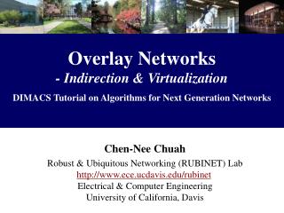
Definition • Network • Define addressing, routing, and service model for communication between hosts • Overlay network • A network built on top of one or more existing networks • Add an additional layer of indirection/virtualization • Change properties in one or more areas of underlying network • Alternative • Change an existing network layer istoica@cs.berkeley.edu
A Historical Example • Internet is an overlay network • Goal: connect local area networks • Built on local area networks (e.g., Ethernet), phone lines • Add an Internet Protocol header to all packets istoica@cs.berkeley.edu
Benefits • Do not have to deploy new equipment, or modify existing software/protocols • Probably have to deploy new software on top of existing software • E.g., adding IP on top of Ethernet does not require modifying Ethernet protocol or driver • Allow bootstrapping • Expensive to develop entirely new networking hardware/software • All networks after the telephone have begun as overlay networks istoica@cs.berkeley.edu
Benefits • Do not have to deploy at every node • Not every node needs/wants overlay network service all the time • e.g., QoS guarantees for best-effort traffic • Overlay network may be too heavyweight for some nodes • e.g., consumes too much memory, cycles, or bandwidth • Overlay network may have unclear security properties • e.g., may be used for service denial attack • Overlay network may not scale • e.g. may require n2 state or communication istoica@cs.berkeley.edu
Costs • Adds overhead • Adds a layer in networking stack • Additional packet headers, processing • Sometimes, additional work is redundant • E.g., an IP packet contains both Ethernet (48 + 48 bits) and IP addresses (32 + 32 bits) • Eliminate Ethernet addresses from Ethernet header and assume IP header(?) • Adds complexity • Layering does not eliminate complexity, it only manages it • More layers of functionality more possible unintended interaction between layers • E.g., corruption drops on wireless interpreted as congestion drops by TCP istoica@cs.berkeley.edu
Applications • Mulicast • This lecture • Mobility • Routing • Addressing • Security istoica@cs.berkeley.edu
Problems with IP Multicast • Scales poorly with number of groups • A router must maintain state for every group that traverses it • Supporting higher level functionality is difficult • IP Multicast: best-effort multi-point deliveryservice • Reliability and congestion control for IP Multicast complicated • Scalable, end-to-end approach for heterogeneous receivers is very difficult • Hop-by-hop approach requires more state and processing in routers • Deployment is difficult and slow • ISP’s reluctant to turn on IP Multicast istoica@cs.berkeley.edu
Overlay Multicast • Provide multicast functionality above the IP layer, overlay or application level multicast • Challenge: do this efficiently • Narada [Yang-hua et al, 2000] • Multi-source multicast • Involves only end hosts • Small group sizes <= hundreds of nodes • Typical application: chat istoica@cs.berkeley.edu
Narada: End System Multicast Gatech Stanford Stan1 Stan2 CMU Berk1 Berk2 Berkeley Overlay Tree Stan1 Gatech Stan2 CMU Berk1 Berk2 istoica@cs.berkeley.edu
Potential Benefits • Scalability • Routers do not maintain per-group state • End systems do, but they participate in very few groups • Easier to deploy • Only requires adding software to end hosts • Potentially simplifies support for higher level functionality • Use hop-by-hop approach, but end hosts are routers • Leverage computation and storage of end systems • E.g., packet buffering, transcoding of media streams, ACK aggregation • Leverage solutions for unicast congestion control and reliability istoica@cs.berkeley.edu
End System Multicast: Narada • A distributed protocol for constructing efficient overlay trees among end systems • Caveat: assume applications with small and sparse groups • Around tens to hundreds of members istoica@cs.berkeley.edu
Performance Concerns Delay from CMU to Berk1 increases Stan1 Gatech Stan2 CMU Berk2 Berk1 Duplicate Packets: Bandwidth Wastage Gatech Stanford Stan1 Stan2 CMU Berk1 Berk2 Berkeley istoica@cs.berkeley.edu
The delay between the source and receivers is small Ideally, The number of redundant packets on any physical link is low Heuristic: Every member in the tree has a small degree Degree chosen to reflect bandwidth of connection to Internet Overlay Tree CMU CMU CMU Stan2 Stan2 Stan2 Stan1 Stan1 Stan1 Gatech Gatech Berk1 Berk1 Berk1 Gatech Berk2 Berk2 Berk2 High latency High degree (unicast) “Efficient” overlay istoica@cs.berkeley.edu
Overlay Construction Problems • Dynamic changes in group membership • Members may join and leave dynamically • Members may die • Dynamic changes in network conditions and topology • Delay between members may vary over time due to congestion, routing changes • Knowledge of network conditions is member specific • Each member must determine network conditions for itself istoica@cs.berkeley.edu
Solution • Two step design • Build a mesh that includes all participating end-hosts • What they call a mesh is just a graph • Members probe each other to learn network related information • Overlay must self-improve as more information available • Build source based distribution trees istoica@cs.berkeley.edu
Mesh • Advantages: • Offers a richer topology robustness; don’t need to worry to much about failures • Don’t need to worry about cycles • Desired properties • Members have low degrees • Shortest path delay between any pair of members along mesh is small CMU Stan2 Stan1 Gatech Berk2 Berk1 istoica@cs.berkeley.edu
Stan1 Stan2 Berk1 Gatech Berk2 Overlay Trees • Source routed minimum spanning tree on mesh • Desired properties • Members have low degree • Small delays from source to receivers CMU Stan2 Stan1 Gatech Berk2 Berk1 istoica@cs.berkeley.edu
Narada Components/Techniques • Mesh Management: • Ensures mesh remains connected in face of membership changes • Mesh Optimization: • Distributed heuristics for ensuring shortest path delay between members along the mesh is small • Tree construction: • Routing algorithms for constructing data-delivery trees • Distance vector routing, and reverse path forwarding istoica@cs.berkeley.edu
Members periodically probe other members at random New link added if Utility_Gain of adding link > Add_Threshold Members periodically monitor existing links Existing link dropped if Cost of dropping link < Drop Threshold Optimizing Mesh Quality CMU Stan2 Stan1 A poor overlay topology: Long path from Gatech2 to CMU Gatech1 Berk1 Gatech2 istoica@cs.berkeley.edu
Utility gain of adding a link based on The number of members to which routing delay improves How significant the improvement in delay to each member is Cost of dropping a link based on The number of members to which routing delay increases, for either neighbor Add/Drop Thresholds are functions of: Member’s estimation of group size Current and maximum degree of member in the mesh Definitions istoica@cs.berkeley.edu
Desirable properties of heuristics • Stability: A dropped link will not be immediately re-added • Partition avoidance: A partition of the mesh is unlikely to be caused as a result of any single link being dropped CMU CMU Stan2 Stan2 Stan1 Stan1 Probe Gatech1 Gatech1 Berk1 Berk1 Probe Gatech2 Gatech2 Delay improves to Stan1, CMU but marginally. Do not add link! Delay improves to CMU, Gatech1 and significantly. Add link! istoica@cs.berkeley.edu
Example CMU Stan2 Stan1 Berk1 Gatech1 Gatech2 Used by Berk1 to reach only Gatech2 and vice versa: Drop! CMU Stan2 Stan1 Berk1 Gatech1 Gatech2 istoica@cs.berkeley.edu
Simulation Results • Simulations • Group of 128 members • Delay between 90% pairs < 4 times the unicast delay • No link caries more than 9 copies • Experiments • Group of 13 members • Delay between 90% pairs < 1.5 times the unicast delay istoica@cs.berkeley.edu
NARADA Summary • End-system multicast (NARADA) : aimed to small-sized groups • Application example: chat • Multi source multicast model • No need for infrastructure • Properties • low performance penalty compared to IP Multicast • potential to simplify support for higher layer functionality • allows for application-specific customizations istoica@cs.berkeley.edu
Other Projects • Overcast [Jannotti et al, 2000] • Single source tree • Uses an infrastructure; end hosts are not part of multicast tree • Large groups ~ millions of nodes • Typical application: content distribution • Scattercast (Chawathe et al, UC Berkeley) • Emphasis on infrastructural support and proxy-based multicast • Uses a mesh like Narada, but differences in protocol details • Yoid (Paul Francis, Cornell) • Uses a shared tree among participating members • Distributed heuristics for managing and optimizing tree constructions istoica@cs.berkeley.edu
Active Networks vs. Overlay Networks • Key difference: • Active nodes operate at the network layer; overlay nodes operate at the application layer • Active network leverage IP routing between active nodes; Overlay networks control routing between overlay nodes • Active Networks advantages: • Efficiency: no need to tunnel packets; no need to process packets at layers other than the network layer • Overlay Network advantages: • Easier to deploy: no need to integrate overlay nodes in the network infrastructure • Active nodes have to collaborated (be trusted) by the other routers in the same AS (they need to exchange routing info) istoica@cs.berkeley.edu