Download
1 / 25
710 likes | 2.18k Views
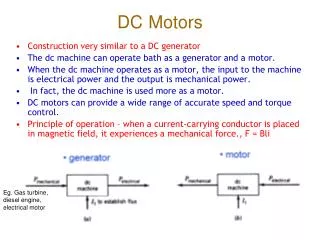
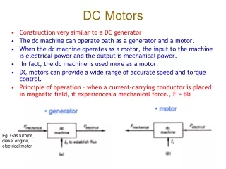
DC MOTORS . SEE 3433 ELECTRICAL MACHINES. DC MOTOR. - Shunt motors - Separately excited - Starter . DC MOTORS. +. -. +. -. DC MOTOR. DC motor. Load torque opposing the motor torque. + V a -. + V f -. +. -. +. -. T m. T load.

E N D
DC MOTORS SEE 3433 ELECTRICAL MACHINES
DC MOTOR - Shunt motors - Separately excited - Starter
+ - + - DC MOTOR DC motor
Load torque opposing the motor torque + Va - + Vf - + - + - Tm Tload Mechanical Load: fans, blowers, Compressors, DC MOTOR DC motor
+ V - + V - + - + - Tm Tload F = mg DC MOTOR DC motor
Hoist DC MOTOR
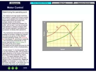
- Some applications require the control the speed DC MOTOR - Some applications require the control the torque - In order to control the torque or speed we need to know the T- characteristics of the motor and the mechanical load Intersections between the two characteristics will determine the operating point
If It + Vt Rcf Ia Ra Rcw Te Tload Mechanical load Shunt motor Vt = IaRa + Ea DC MOTOR It = Ia + If Ea = k Te = kIa k = Vt - IaRa
Three possible methods of speed control: Field flux Armature voltage Vt Armature resistance Ra
Varying Vt TL Vt↓ Te Requires variable DC supply
Varying Ra Ra↑ TL Te Simple control Losses in external resistor
Varying ↓ TL Te Not possible for PM motor Maximum torque capability reduces
Armature voltage control Field flux control Te Maximum Torque capability base Method of speed control in DC motor drives Armature voltage control : retain maximum torque capability Field flux control (i.e. flux reduced) : reduce maximum torque capability For wide range of speed control 0 to base armature voltage, above base field flux reduction
Te Maximum Torque capability base
Pmax Constant torque Constant power base P Te 0 to base armature voltage, above base field flux reduction P= EaIa,max = kaIa,max Pmax = EaIa,max = kabaseIa,max 1/
0 to base armature voltage, above base field flux reduction
If It + Vt Rcf Ia Ra Rcw 0 to base armature voltage, above base field flux reduction BUT there are problems !
If It + Vt Rcf Ia Ra Rcw 0 to base armature voltage, above base field flux reduction Controlling Vt will also affect If Controlling If via Rcf caused losses I2R
DC supply for armature DC supply for field 0 to base armature voltage, above base field flux reduction Separately Excited DC motor What if we have an AC supply ?
3-phase AC source Armature voltage control Field voltage control 0 to base armature voltage, above base field flux reduction Separately Excited DC motor AC to DC converter + Vdc - + Vdc - AC to DC converter
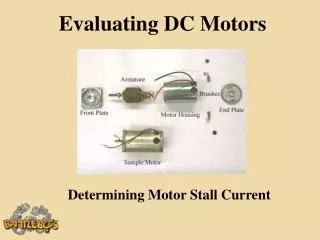
Starter in DC Motor • At stand-still, w = 0 Ea = 0 Ra Ia + Vt – eg, Vt = 100, Ra = 0.1 Ia = 1000 A !
Starter in DC Motor • We can limit Ia at start-up by: 1) Controlling Vt using variable supply – e.g. using power electronics converter 2) Adding external resistor known as starter Ra Ia + Vt – + Ea – When Ea = 0 Rst • As speed builds up (so too Ea), Rst is gradually reduced
Starter in DC Motor • As speed builds up (so too Ea), Rst is gradually reduced Ia Starter circuit 4 3 2 1 Imax Imin 1 2 3 4 t (s) speed t (s)
Starter in DC Motor Practical Starter circuit