Download
1 / 53
600 likes | 1.56k Views
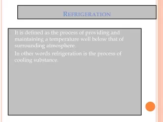
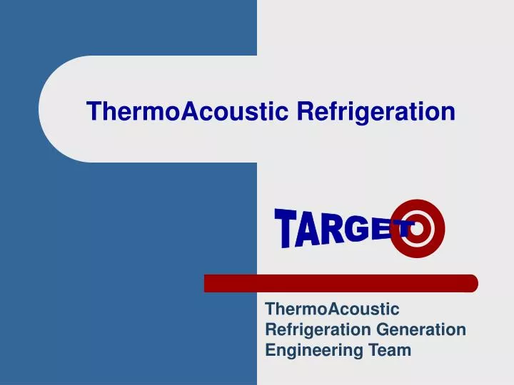
ThermoAcoustic Refrigeration. ThermoAcoustic Refrigeration Generation Engineering Team. TARGET. TARGET. Team Members . Trevor Bourgeois Mike Horne Peter Smith Erin MacNeil Supervisor – Dr. Murat Koksal. TARGET. Design Description. Thermoacoustic Refrigerator Unpressurized System

E N D
ThermoAcoustic Refrigeration ThermoAcoustic Refrigeration Generation Engineering Team TARGET
TARGET Team Members • Trevor Bourgeois • Mike Horne • Peter Smith • Erin MacNeil • Supervisor – Dr. Murat Koksal
TARGET Design Description • Thermoacoustic Refrigerator • Unpressurized System • Air as Gas Medium • Loudspeaker as Acoustic Driver • Variable design (stacks) • Advantages of Thermoacoustic Refrigeration • No Environmentally-Harmful Refrigerants • Mechanically Simple
TARGET Summary of Fall Term • Work to understand Theory • Development of Mathematical Model • Construction of two Prototypes • Standing wave created • No DT • Identification of Stack as most important component
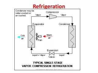
TARGET Main Prototype Components • Speaker • Gas • Tube • Stack • Heat Exchangers
Considerations Power Capacity Frequency Response Choice 10 inch Operates At Low Frequencies (100 Hz) 400 W Maximum Power TARGET Speaker
Considerations Physical Properties Sealing Cost Choice Air Atmospheric Pressure TARGET Gas Medium
Considerations Length Diameter Sound Reflection Low Acoustic Losses Sound Transmission Choice 1.5” PVC Tube Flat End TARGET Tube
TARGET Stack • Considerations • Gap Size • Material properties • Material thickness • Location • Length • Does not impede wave • Choice • Paper • Aluminum Screen
Considerations Material Type Choice Aluminum Water Circulated TARGET Heat Exchangers
TARGET Stack • Solid Porous Material • Give And Takes Heat From Gas • Heat Transfer • DT Across
TARGET Design Considerations • Gap Size • Solid Thickness • Position • Length • Ability Of Sound To Pass Through • Physical Properties
TARGET Stack Designs • Foil • Paper • Foam • Lexan • Screen
TARGET Foil • Aluminum Foil • Crimped • Rolled Up Around Centre Post
TARGET Foil
TARGET Paper • Couragrated Paper • Rolled Up
TARGET Paper
TARGET Foam • Open Cell Foam • Cut To Approximate Shape • Tape To Hold Two Pieces Together
TARGET Foam
TARGET Lexan • Strips Thin Lexan • Monofilament Fishing Line Used As Spacers • Rolled Up Around A Pencil
TARGET Lexan
TARGET Screen • Aluminum Screen • Punch To Cut Circles • Many Layers
TARGET Screen
To better understand how measurements were taken, we will look at the stack area • Pressure measurements were taken in the tube by attaching pressure transducers in the locations shown in red • Temperature measurements were taken using thermocouples. They were fed through the tube through small drilled holes and mounted on the stack face. They are shown in blue. Thermocouples Pressure Transducers TARGET Experimental Setup
The first experiment conducted was a test to determine the operating frequency of the design • A frequency scan in increments of 20 Hz was applied to determine the frequency that creates the highest pressure values in the tube • Two high pressure zones were evaluated from the experiment and are located in the 130 Hz and 220 Hz region shown in red TARGET Maximum Pressure vs. Frequency
Once an operating frequency was selected from the previous experiment, temperature tests were conducted for the 130 Hz zone • Up until this point in the group was not convinced that temperature results could be obtained • Fortunately temperature results appeared within a short time period of 10 seconds • Each stack was tested, with the results better described on the following slide TARGET Stack Temperature vs. Time @130Hz
Stack alternatives were Aluminum Screen, Lexan, Aluminum Foil, Paper, and Foam • After extensive testing of all stack options, the following maximum and minimum temperature values were obtained • Results favor the Aluminum Screen and Paper stack because of their low cold side temperature, and large temperature difference 48 C 44 C 44 C 42 C 36 C 25 C 24 C 21 C 18 C 18 C TARGET Stack Temperatures at 36 Watts Aluminum Foil Aluminum Screen Foam Paper Lexan Temperature Difference 19 C 30 C 18 C 15 C 26 C
A scan of temperature difference across the stack at various frequencies was also conducted • A comparison of this graph with the previous pressure vs. frequency scan reveals the correlation between pressure and temperature results, although it is surprising that a temperature difference is possible at frequencies other than optimum TARGET Temperature vs. Frequency
The effectiveness of each stack to create a temperature difference was also investigated • From this graph, we can see that the Paper and Aluminum Screen versions were again top performers, but this plot also tells us the effectiveness of each stack to create a temperature difference • Example, twice as much power for the Lexan stack to create a temperature difference equivalent to that of the aluminum foil TARGET Temperature vs. Speaker Power
The effects of temperature vs. radial distance of the stack was also examined • Thermocouples were placed at various locations on the hot stack face • The two best stack options were tested by this method – the Aluminum Screen and Paper model • It was discovered that the Paper stack had temperature deviations in the radial direction, while the Aluminum Screen remained constant radially – values are indicated in the slide • It can be determined that the Aluminum Screen version has higher radial heat transfer than that of the Paper stack Thermocouple Locations 46.4 41.7 46.7 39.5 46.4 39.2 Aluminum Screen Paper TARGET Temperature vs. Radial Distance
From the experiments conducted, the results were used to properly rank each choice by the pairwise ranking method, and aggregate scoring method • Variables considered were the compatibility into the design, cost, low side temperature, manufacturability, power and efficiency, and temperature difference • The pairwise ranking was first applied to determine importance of each variable • A group evaluation determined that compatibility and temperature difference were the most important factors in the design of an effective stack TARGET Stack Ranking • Pairwise Ranking Method • Important Attributes Determined • Ranked According to Importance For Each Stack
An aggregate scoring system was then applied using the pairwise data • This system uses a scoring system based on effectiveness to meet each variable • As a group, it was determined that the Aluminum Screen and Paper stacks were most likely to meet the design requirements stated earlier with scores significantly greater over the other choices TARGET Stack Ranking • Aggregate Scoring System • 10 = Highly Effective 0 = Not Effective
Well, most of you are wondering how we are actually going to cool an air space with the experimental results • The left stack shown, indicates what the group thought was going to happen to the stack before the experimentation, where we achieve an equal temperature difference about the ambient temperature • Experimental results show that this is not the case (shown on the right) where a hot side is achieved with a small drop in temperature for the cold side (3 degrees below ambient) • Regardless, it is believed that once a heat exchanger is implemented (to remove heat), it will reduce the hot side temperatures and cold side temperatures accordingly • To further discuss the adaptation of the heat exchanger into our design, I will now pass the presentation over to Pencil Pete Remove Heat Best Temperature Values 48 C 17 C TARGET Stack Temperature Results
Hot Side Heat Exchanger Wooden Cartridge Cold Side Heat Exchanger TARGET • We decided to go with two HE • From experimentation we believed that if…. • Zoom on top of model • Developed two heat exchangers separated by wooden cartridge • Acts as insulating material to prevent conduction between the two HE. • Now like to present the evolution of our HE design. Heat Exchanger • Cold Side • To use the cold temperature produced and cool a cold space • Hot Side • Experiments: heat conduction from hot side to cold side • If we cool the hot side, we will be able to obtain a colder cold side
Four Bolt Holes Floating fastener assembly Center Hole To hold part of the stack TARGET Heat Exchanger Evolution • Peter: • The HE must all be compatible with our present design. • All our designs will consist of a circular disk will four holes designed for a floating fastener assembly and a center hole to hold part of the stack. Heat exchanger must be compatible with our present design
TARGET Heat Exchanger Evolution Manufacturing • Drill three thru holes • Intersect at right angles • Four ends tapped and plugged • Front two ends tapped for a 1/8” NPT thread Drill Thru Channel Design
TARGET Heat Exchanger Evolution Peter: We weren’t confident that we could get a long enough drill bit and if so prevent the tool from wandering Pros:Few manufacturing steps Low cost operation Cons: Long enough drill bit Possible tool wandering Drill Thru Channel Design
Tube Insert TARGET Heat Exchanger Evolution Manufacturing • CNC machine a pocket for the tube insert • Tube insert • Machined block • Connects five 1/16” diameter tubes. • Seal with silicone • Drill and tap two ends for a 1/8” NPT thread Tube Flow Design
TARGET Heat Exchanger Evolution Pros:Greater heat transfer rate Cons:Higher manufacturing costs Longer build time Sealing Larger pump ( ) Tube Flow Design
TARGET Heat Exchanger Evolution Manufacturing • CNC – end mill curved profile • Thickness of wall is 2mm • Front two ends drill and tap for a 1/8” NPT thread CNC Milled Channel Design
TARGET Heat Exchanger Evolution Pros:Better rate of heat transfer than the first design. Lower machining costs than the second design. Cons:Sealing CNC Milled Channel Design
Wooden Cartridge Reservoir • Peter: • Plastic tubing was chosen to transport the water from the pumps to the heat exchangers and from the heat exchangers to the cold space or reservoir. • The plastic tube was chosen based on its flexibility and ease of assembly with the fittings. TARGET Heat Exchanger Setup Hot Side Heat Exchanger Cold Side Heat Exchanger Large Reservoir to keep water at a constant temperature
Wooden Cartridge Cold Space TARGET Heat Exchanger Setup Hot Side Heat Exchanger Represents our refrigerating capacity Cold Side Heat Exchanger
+ve Slope -ve Slope +veSlope -ve Slope TARGET Heat Exchanger Experiments 5.5°C
Cold Space Cold Space Cooling From Prototype Cooling from atmosphere TARGET Heat Exchanger Experiments 1.2°C in 30 minutes 4.8°C in 30 minutes
Heat removal rate of 16.7W Speaker drawing power at 90.25W Cold Space Cooling From Prototype TARGET Heat Exchanger Experiments 3.6°C in 30 minutes COP = 0.185
(17 º C) (16.7 W) TARGET Comparison with Project Goals • Less than ½ meter long, less than 20lb • DT of 5-10ºC below ambient • Sound Insulation • Introduce Heat Exchangers • 10-20 Watts Cooling • Build for less than $2,000.00 • User’s Manual
TARGET Recommendations • Theoretical Work • Calculate Operating Frequency • Heat Exchanger Calculations
TARGET Recommendations • Theoretical Work • Experimentation • Stack Gap Size • Stack Location • Stack Length
TARGET Recommendations • Theoretical Work • Experimentation • Equipment Improvements • Pressure Transducers • Signal Generator