Download
1 / 52
640 likes | 1.98k Views
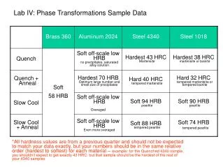
Sample Preparation, Data Collection and Phase-ID using Powder XRD. Pamela Whitfield Canadian Powder Diffraction Workshop. Horses for Courses…. Data quality required depends on what you want to do with it Phase-ID has less stringent requirements on both sample prep and data collection

E N D
Sample Preparation, Data Collection and Phase-ID using Powder XRD Pamela Whitfield Canadian Powder Diffraction Workshop
Horses for Courses… • Data quality required depends on what you want to do with it • Phase-ID has less stringent requirements on both sample prep and data collection • Quantitative phase analysis, Rietveld analysis and structure solution require careful sample prep but can require different data collection regimes • I’ll mostly cover requirements for phase ID but will touch on considerations for other techniques… • I did a presentation last week concentrating more on quantitative analysis; if you’re interested just ask and you can have a copy
Questions to ask • What is in your sample? • Organics often better collected in transmission • Fluorescence can cause problems in data quality • How much have you got? • Very small quantities • capillary geometry? (not an option for many people) • Smear mount • We’ll assume conventional Bragg-Brentano reflection geometry for most of the rest of this presentation • What kind of instrument have you got access to? • If you have a choice which is the best?
What matters for phase-ID? • Peak positions most important • Relative intensities secondary • but very important for Rietveld, etc…. • If wanting to do search-match it is useful if the phases exist in the PDF database!
Where to start? • What affects peak positions? • What affects relative intensities? • Preparing the samples • Different types of sample holders
Peak positions • Zero point error - is the system properly aligned? • Sample displacement - is the sample too high/low? (0.1mm error will shift peaks approx 0.045°) • Sample transparency • if the X-rays penetrate a long way into the sample can get a ‘sample displacement’ even if the height is perfect • again not an issue for parallel-beam systems • if necessary use a thin sample to avoid transparency peak shifts • relative intensities will be affected Note: convention is that –ve sample displacement = sample too high Not an issue for parallel beam systems
Relative intensities • Particle statistics (grain size) • Preferential orientation • Crystal structure • Microabsorption (multiphase samples)
Sample-related problems • Grainy samples or ‘rocks in dust’ • Microabsorption • a serious issue for quantitative analysis and could fill a talk by itself! • Preferential orientation
Crystallite size range Diameter 15-20mm 5-50mm 40mm 10mm 5-15mm 1mm <5mm Crystallites / 20mm3 5.97 × 10⁵ 3.82 × 10⁷ 3.82 × 10¹⁰ Intensity reproducibility 18.2% 10.1% 2.1% 1.2% No. of diffracting crystallites 12 760 38000 “Grainy” Samples • Issue of graininess relates to particle statistics • Particle statistics is what makes a powder a true powder! • 600 mesh sieve = <20 mm Comparison of the particle statistics for samples with different crystallite sizes Reproducibility of the intensity of the quartz (113) reflection with different crystallite sizes
How to improve particle statistics • There are a number of potential ways to improve particle statistics • Reduce the particle size (without damaging crystallites!) • Increase the area illuminated by X-rays • Divergence angle • Watch for beam overspill at low angles • Rotate samples • but not a replacement for proper sample prep! McCrone mill = good Mortar and pestle = bad
How does it affect your data? • Reproducibility of data can be gauged by running repeat samples after reloading sample each time • Unmicronized sample: MgO only appears in 1 sample out of 3 periclase Overlay of 3 repeat patterns from un-micronized cement Overlay of 3 repeat patterns from micronized cement
Microabsorption • Microabsorption is the thing that causes most nightmares for analysts doing quantitative phase analysis • Caused by a mixture of high and low absorbing phases • High absorbers • beam absorbed at surface • only fraction of grain diffracting • relative intensity underestimated • QPA too low • Low absorbers • beam penetrates deeper • more diffracting volume • relative intensity overestimated • QPA too high
What can you do about it? • Change radiation? • Absorption contrast changes with energy • Higher energy X-rays often less problematic • Use neutrons? • Not usually practical but a ‘gold standard’ • Use the Brindley correction? • Can be dangerous • Need to know absorption of each phase • Need to know particle (not crystallite!) size for each phase • But assumes spherical particles with a monodisperse size distribution • Usually unrealistic!
Effect of particle size • Brindley proposed that a maximum acceptable particle size for QPA can be calculated by: m = linear absorption coefficient (LAC)
The scale of escalating despair! • Brindley also devised a criteria for whether you should be ‘concerned’ about microabsorption • mD = linear absorption coefficient x particle diameter • Fine powders • mD < 0.01 negligible m-absorption • Medium powders • 0.01 < mD < 0.1 m-absorption present – Brindley model applies • Coarse powders • 0.1 < mD < 1 large m-absorption – Brindley model estimates the effect • Very coarse powders • mD > 1 severe m-absorption – forget it!
Preferential Orientation • Preferential orientation (PO) is most often seen in samples that contain crystallites with a platey or needle-like morphology. • Particular culprits • Plates • mica • clays • some carbonates, hydroxides e.g. Ca(OH)2 • Needles • wollastonite • many organics • The extent of the orientation from a particular sample depends greatly on how it is mounted
Different preparation techniques • Top-loading • Flat-plate • Back-loading • Side-loading • Capillary
Top-loading • Simplest but most prone to inducing preferential orientation • Sometimes orientation induced deliberately, e.g. ID of clays Alternative holders such as zero background silicon or quartz usually top-loading as well
Flat plateaka: Smear mount • Used with very small samples (phase-ID , Rietveld ) • Sample adhered to zero background plate using some form of binder/adhesive that doesn’t have any Bragg peaks • Hairspray! Spray ~12” from holder makes a sticky surface – my favourite • PVA • Slurry with ethanol or acetone – tricky to get right consistency • Some quartz plates can show a sharp reflection when spun Silicon zero background plate Quartz zero background plate Gem Dugout a commonly used source for zero background plates (www.thegemdugout.com)
Side-loading • I don’t have one of these! • Basic principle….. plug powder sample holder glass slide
Capillaries • Probably best way to prevent orientation in platey materials • not much good unless you have a capillary stage! • Not 100% effective with needle-like materials though • Capillaries range in diameter from 2mm to 0.1mm • Made from either borosilicate or quartz glass • Only useful where absorption is low • Small diameters can be extremely fiddly to fill! 0.2 mm 1 mm
Example – hydrated cement • Hydrating cement produces beautiful plates of portlandite, Ca(OH)2 • Breaking up these plates (changing their aspect ratio) will reduce their tendency to lie flat, i.e. orientate • What happens if you can’t…….?
15 day cement – top-loaded and capillary Capillary Top-loaded • Portlandite orientation very obvious in top-loaded sample • wrong reflection is the 100% peak! Effect on the QPA XRD results. Kinetics from reflection data nonsensical. N.B. Texture Index of 1 = perfect powder.
Corrections for PO in Rietveld software • Two different corrections exist in most software to correct orientation during Rietveld analysis • March-Dollase (MD) • Single variable but an orientation direction must be supplied by the analyst • Spherical Harmonics (SH) • VERY powerful approach – can increase SH ‘order’ to fit increasingly complex behaviour • Multiple variables but no orientation direction required • Number of variables increase with reducing cell symmetry • Be very careful in multiphase systems (e.g. cements, rocks) with overlapping peaks • Negative peaks are very common and very meaningless!
Data collection strategies • For Rietveld analysis guidelines were published by McCusker et al in 1999 but still a good reference • Choose beam divergence such that the beam doesn’t overspill the sample at low angle • remember the under-scan when a PSD is used! • You’re first datapoint may be at 10° 2q but the instrument may start at 8°! (ENeqV1_0.xls very handy for working out correct divergence) (http://ig.crystallography.org.uk/spreadsh/eneqv1_0.xls) • Step size of approx FWHM/5 • Too small = wasting time and producing noisy data • Too coarse = chopping intensity and peaks not modelled properly
Experiment optimization • ‘Horses for courses’ – collect data fit for purpose • Data for phase-ID does not have to be of the same quality as for structure solution, etc • Most common mistake among users • too small step size for sample 0.01º step, 1s count Rwp = 15.2% 0.02º step, 2s count Rwp = 12.0% 2 different datasets from quartz stone – both experiments took 25 seconds Smaller Rwp corresponds to a better fit.
Peak-to-background • A number of things can affect the peak-to-background in a pattern • air-scatter at low angles • use air-scatter sinks if needed • nanoparticles have lower intrinsic peak heights • not much you can do here • eventually Rietveld results are no longer meaningful • capillaries always have higher background • subtracting capillary blank can improve this but careful not to distort counting statistics • fluorescence is the main cause of poor peak-to-background… • Rietveld refinement round robin suggested a minimum P/B value of 50 for accurate structural parameters….
Why does background matter? • With a high background the uncertainty in the background parameters increase (often use more parameters as well) • uncertainty in the peak intensities increases → greater uncertainty in structural parameters and quantitative phase analysis Which line would you choose?
1300 CuKa - Li1.15Mn1.85O3.9F0.1 1200 1100 1000 900 800 Lin (Counts) 700 600 500 400 300 200 100 0 15 20 30 40 2-Theta - Scale Fluorescence • Fluorescence even adversely affects phase-ID detection limits • secondary monochromator on conventional system is an effective filter there is a real peak here! No monochromator Properly aligned monochromator/mirror 50 60 70 80
Fluorescence – what to do about it? • With a PSD a monochromator not possible – Vantec data with CoKa CoKa - LiMn1.5Ni0.5O4 Which dataset do you prefer?
Fluorescence cont. • Can improve data significantly by adjusting the detector discriminator window P/B = 13.4 Rescaled to normalize background P/B = 4.5 Sacrifice intensity to improve P/B ratio P/B = 4.2 P/B still along way off 50. Change radiation or instrument.
Problematic sample:Phase-ID • Aspirin • organic sample • large transparency effects in reflection (peak shifts & poor resolution) • use smear mount Comparison of data from aspirin using lab top-loading and capillary compared to synchrotron data.
Problematic sample: Quant Analysis • FeS + Mg(OH)2 + SiO2 • CuKa • Ground or unground? • particle statistics • Microabsorption (FeS) • ideally switch to CoKa • Fluorescence (FeS) • high background • monochromator, energy-discriminating detector, switch to CoKa • Preferential orientation (Mg(OH)2) • Extinction? (SiO2) • Micronize!!!! • All of these problems are reduced by micronizing to sub-micron particle/crystallite size
Problematic sample: Rietveld analysis • LiMn1.4Ti0.1Ni0.5O4 (lithium battery cathode material) • Mn fluoresces with both CuKa (1.54Å) and CoKa (1.79Å)! • Worse with CoKa in this case • Use a monochromator or energy discriminating detector • Good peak-to-background, but... • Fluorescence is still there even if you can’t see it • Very high absorption impacts particle statistics (X-rays only penetrate a few 10s of microns) • Solution by changing tube? • CrKa 2.29Å (unusual, high air scatter/attenuation and limits lower d-spacings attainable) • FeKa 1.94Å (very unusual and low power tubes) • MoKa 0.71Å (unusual and beta-filter artefacts visible)
LiMn1.4Ti0.1Ni0.5O4 Co Cu P/B = 4.5 P/B = 9.4 Mo Cr P/B = 84 P/B = 87 (P/B = 54 without air-scatter sink to reach angles >100) A primary monochromator would get rid of this high angle tail
Variable Count Time • One problem with XRD is the drop in intensity with increasing 2q • Most of the ‘information’ is at the higher angles but least-squares practically ignores it Data from the mineral stichtite
VCT continued • Error in intensity = intensity (Poisson statistics) • can reduce error (and increase weighting) by counting for longer…. • In practice split into ranges and double count time for each range (can increase step size to partially compensate for increased time) Raw VCT capillary data for stichtite Data reformatted into ASCII format xye file Remember if subtracting background (e.g. capillary blank) that the error is original intensity!
VCT dataQuantitative analysis • Possible to improve detection limits in quant analysis by counting for longer where minor phases expected Fixed count time Variable count time (normalized) Example from presentation by Lachlan Cranswick
VCT dataStructure refinement • You can extract more structural details if reflections still resolvable up to high angles Jadarite structure with thermal ellipsoids
Phase-ID • Phase-ID usually undertaken using vendor-supplied software with the Powder Diffraction Database (PDF2 or PDF4) • The database is not free so budget accordingly • PDF4 requires yearly renewal but has more features • PDF2 good enough for search-match and OK for 10 years • The PDF2 uses XRD ‘fingerprints’ – if they haven’t been deposited they won’t show up • PDF2 entries are allocated a ‘quality mark’ but occasionally the newer ones are actually worse! • Experimental quality marks ‘*’ > ‘I’ > ‘A’ > ‘N’ > ‘D’ • Calculated from ICSD, etc ‘C’ • Background subtraction recommended before search-match if it is high but don’t bother with Ka2 stripping, etc
Phase-ID • Improve your odds in the search-match • make a sensible guess as to the likely elements • does your sample really have plutonium in it?! • if you have elemental analysis results then use them • but consider possibility of amorphous phases! Search-match in EVA on a sample of zircon
Use common/chemical sense • don’t believe results just because the computer tells you • even oxygen has entries in the PDF2! • Where software supports it ‘residue’ searches can be helpful in identifying minor phases
Minor peaks - make sure they aren’t Kb or tungsten lines! • vendor software can often identify these (e.g. EVA below) WLa CrKa CrKb
No luck – what next? • Do you have a large systematic error in the data? • check your diffractometer alignment if not sure • modern search-match software can cope with a reasonable error but it has limits • Look for possible analogues which may appear in the PDF2 • LaCoO3 similar to LaNiO3 with slightly different lattice parameters • analogues may have significantly different relative intensities • however: LiMnO2 (Pmmn) completely different from LiCrO2 (R-3m) LiMnO2 LiCrO2 LaNiO3, R-3c a = 5.456, c = 13.143Å LaCoO3, R-3c a = 5.449, c = 13.104Å
Getting desperate yet? • Put the sample under optical microscope with polarizers • does it seem to have the number of phases you expect? • If it contains Fe or Co try a magnet! • Possible contamination • mortar and pestle not clean • material from micronizer grinding elements (newer corundum elements not as good as the older ones – use agate) • Last possibility to consider…. • maybe you have found a new phase
Conclusions… • Use the appropriate sample mounting technique for the sample and the data requirements • Graininess, microabsorption and preferential orientation are all related to particle and crystallite size • Do yourself a big favour by micronizing your sample! • Preferential orientation can be corrected during analysis but the others can’t • The assumptions required by the Brindley correction are never met in real life
There are times when the newest diffractometer (PSD, etc) isn’t the best one for the job! • No such thing as the perfect configuration for everyone • VCT data can help in a number of ways • improve the detection limit for minor phases • significantly improve the quality of a structure refinement • If you don’t remember anything else remember this! • think about your samples! • a one size fits all approach doesn’t work!
Acknowledgements • Ian Madsen (CSIRO) • I couldn’t improve on his explanation of microabsorption so I used it! • Responsible for the QPA XRD round robin samples which still give people nightmares • Lyndon Mitchell (NRC-IRC) • cement samples