Download
1 / 48
660 likes | 1.28k Views
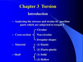
Torsion. introduction. A moment acting about a longitudinal axis of the member is called a torque, twisting moment or torsional moment, T. Torsion may arise as the result of:

E N D
introduction • A moment acting about a longitudinal axis of the member is called a torque, twisting moment or torsional moment, T. • Torsion may arise as the result of: • Primary or equilibrium torsion: occurs when the external load has no alternative to being resisted but by torsion. Examples: curved girders and the three structures shown in Figure.
introduction • secondary or compatibility torsion: in statically indeterminate structures from the requirements of continuity. Neglecting this torsion will not cause problems because: (1) the shear and moment capacities of the beam are not reduced by small amounts of torque, and (2) the stressing of adjacent members as the beam twists permit a redistribution of forces to these members and reduces the torque that must be supported by the beam.
Shearing stresses due to torsion in un-cracked members • Torsion subject is usually neglected in teaching courses of strength of materials. The average designer does not worry about torsion although most structures are subjected to torsional stresses. However, reducing the factor of safety over the past years resulted in increasing situations were torsional failures occur with the result that torsion is a more common problem. The following is an introduction to the elastic torsion theory as given in mechanics of materials books.
Behavior of Circular Sections • Although circular sections are rarely a consideration in normal concrete construction, a brief discussion serves as a good introduction to the torsional behavior of other types of sections. • The basic assumptions are: 1. Plane sections perpendicular to the axis of a circular member remains plane after torque is applied. 2. Radii of section stay straight (without warping). As a result of applying the torsion shearing stresses are set up on cross sections perpendicular to the axis of the bar as shown in Fig.
Behavior of Circular Sections • Shear stress is equal to shear strain times the shear modulus in the elastic range. If r is the radius of the element, J = πr4 /2 its polar moment of inertia, and max is the maximum elastic shearing stress due to elastic twisting moment T, then from basic strength (mechanics) of material courses
Behavior of rectangular sections Such sections do not fall under the assumptions stated before. They warp when a torque is applied and radii don't stay straight. As a result axial as well as circumferential shearing stresses are generated. For a rectangular member, the corner elements do not distort at all (corners=0) and the maximum shear stresses occur at the midpoints of the long sides as shown in Figure. These complications plus the fact that reinforced concrete sections are neither homogeneous nor isotropic make it difficult to develop exact mathematical formulations based on the physical models.
Behavior of rectangular sections • From the mathematical theory of elasticity the magnitude of the maximum shear stress , at midpoint of the long side, due to a torque T as a function of the ratio y to x (long to short sides) is given by • Where α varies from 0.208 for y/x=1 (square bar) to 0.333 for y/x= (infinity wide plate)
Hollow members • Consider a thin‑wall tube subjected to a torsion T as shown in Fig. 8.5. If the thickness of the tube is not constant and varies along the perimeters of the tube, then equilibrium of an element like that shown in Figure b requires: • Where q is referred to as the shear flow and is constant.
Hollow members In order to relate the shear flow q to the torque T, consider an element of length ds as shown. This element is subjected to a force qds and but rds = twice the area of the shaded triangle, then where Ao is the area enclosed by the middle of the wall of the tube. From the above equation max occurs where t is the least.
Examples • Read example 7.1 in textbook • Example 2: compute the shear stress, , at the wall and at the lower flange in the section shown below, due to an applied torque of 1000kN.m.
Principal stresses due to torsion Principal tensile stresses eventually cause cracking that spirals around the body, as Shown by the line A-B-C-D-E In reinforced concrete such a crack would Cause failure unless it was crossed by reinforcement. This generally takes the form of longitudinal bars in the corners and closed stirrups.
Principal stresses due totorsion and shear The two shear stresses components add on one side face (front side) and counteract each other on the other. As the result inclined cracking starts on AB and extends across the flexural tensile face. If bending moments are large, the cracks will extend almost vertically across the back face. The flexural compression zone near the bottom prevents the cracks from extending full height.
Behavior of RC members subjected to torsion When a concrete member is loaded in pure torsion, shear stresses develop. One or more cracks (inclined) develop when the maximum principal tensile stress reaches the tensile strength of concrete. The onset of cracking causes failure of an unreinforced Member. Furthermore the addition of longitudinal steel without stirrups has little effect on the strength of a beam loaded in pure torsion because it is effective only in resisting the longitudinal component of the diagonal tension forces. A rectangular beam with longitudinal bars in the corners and closed stirrups can resist increased load after cracking as shown in figure.
Combined torsion, moment and shear Test results for beams without stirrups loaded with various ratios of torsion and shear are plotted in figure. The lower envelope of data is given as: Where Vcu =inclined cracking shear in the absence of torque. Tcu = the cracking torque in the absence of shear.
Behavior of RC members subjected to torsion After the cracking of a reinforced beam, failure may occur in several ways. The stirrups, or longitudinal reinforcement, or both, may yield, or, for beams that are over-reinforced in torsion, the concrete between the inclined cracks may be crushed by the principal compression stresses prior to yield of the steel. The more ductile behavior results when both reinforcements yield prior to crushing of the concrete. Figure shows that ultimate strength of rc beams were the same for solid and hollow beams having the same reinforcement.
Space Truss Analogy Theory Assumptions: 1. Both solid and hollow members are considered as tubes. 2. After cracking the tube is idealized as a hollow truss consisting of closed stirrups, longitudinal bars in the corners, and compression diagonals approximately centered on the stirrups. The diagonals are idealized as being between the cracks that are at angle , generally taken as 45 degrees for RC.
The cracking pure torsion Knowing that the principal tensile stress equal to the shear stress for elements subjected to pure shear, thus the concrete will crack when the shear stress equal to the tensile capacity of cross section. If we use conservatively 0.333√fc as tensile strength of concrete in biaxial tension-compression, and remembering that Aomust be some fraction of the area enclosed by the outside perimeter of the full concrete cross section Acp. Also, the value of t can, in general, be approximated as a fraction of the ratio Acp/Pcp, where Pcp is the perimeter of the cross section. Then, assuming a value of Ao approximately equal to 2Acp /3, and a value of t=3 Acp/4Pcp. Using these values in Eq. above yields: Note: tensile strength under biaxial compression And tension is less than in uniaxial tension (≈0.67).
The cracking torsion In combined shear and torsion, if T=0.25Tcr , the reduction in the inclined cracking shear is: This was deemed to be negligible. The threshold torsion below which torsion can be ignored in a solid cross section is: For isolated beam, Acp is the area enclosed by the perimeter of the section including the area of any holes. Pcp is the perimeter of the section. For a beam cast monolithically with the floor slab, ACI 11.5.1 defines the overhanging flange width to be included in the calculation of Acpand Pcpas shown
The cracking torsion Note: a lower limit (one fourth of derived) is placed for finding Tcr in the previous equation for conservative purposes to deal with equilibrium torsion. The derived value is permitted according to ACI code for compatibility torsion. Thin-walled hollow sections The interaction diagram between shear and torsion approaches a straight line as Ag /Acp decreases. Where Agis the area of concrete only in a cross section and Acp is the total area enclosed by the perimeter. As a result, a value of T=0.25Tcr would reduce the inclined cracking shear to 0.75Vcr. So the ACI code replaces Acp in the previous equation of Tth for solid section with Ag , so
Area of stirrups for torsion Reinforced concrete beams subjected to torsion will have a decrease in torsional strength after concrete cracks to about half of that of the uncracked member, the remainder being now resisted by the reinforcement. As the section approaches the ultimate load, the concrete outside the stirrups cracks and begins to spall off. Thus, the area enclosed by the dimensions xo and yo is now the one that resists torsion. The xo and yodimensions as shown in Figure a are measured to the centerline of the outermost closed transverse reinforcement and hence the gross area Aoh = xoyo and the shear perimeter ph = 2(xo + yo).
Referring to Figure b, the torsional resistance can be represented as the sum of the contributions of the shears in each of the four walls of the equivalent hollow tube. Following a procedure similar to that used for shear, the quilibrium of a section of the vertical wall with one edge parallel to a torsional crack with angle θ can be evaluated using the shown Figure as:
Area of stirrups for torsion Where: At = area of one stirrup leg of a closed stirrup. = yield strength of transverse reinforcement s = stirrup spacing. Combining previous two equations gives: It has been found experimentally that, after cracking, the effective area enclosed by the shear flow path is somewhat less than the value of xoyo =Aoh , instead ACI recommends using 0.85Aoh with Ao substituted for Aoh. The value may be taken between 30-60 degrees. ACI 11.5.3.6 suggests that may be taken as 45 degrees, because this corresponds to the angle assumed in the derivation of the equation for designing stirrups for shear.
Torsional longitudinal reinforcement The longitudinal reinforcement Al must be proportioned to resist the longitudinal tension forces that occur in the space truss.
Combined shear and torsion The previous derivations for stirrups and longitudinal reinforcement in space truss analogy assumed all the torsion was carried by the reinforcement without any torsion carried by the concrete. When shear and torsion act together, the 1995 and subsequent ACI codes assume that: Vn = Vc + Vs Tn = Ts
Maximum shear and torsion A serviceability failure may occur if the inclined cracks are too wide at service loads. The limit on combined shear and torsion in ACI 11.5.3.1 was derived to limit the service-load crack widths. For a hollow section as shown in Figure the two stresses add at A and yield: For a member with a soild section, experimental results shows that above equation is overconservative, a better representation is given by: The combined shear stress due to shear force and torsional moment is limited to the same criterion for shear capacity as explained in Chapter 6.
Combined moment and torsion • As shown in figure below: in the tension zone tensile forces add together contrary to compression zone. ACI 11.5.3.9 allows the area in compression zone to be reduced by an amount equal to M u /0.9dfy
Design Procedure for Combined Shear, Torsion and Moment Step 1. Calculate the factored bending moment diagram or envelope for the member. Step 2. Select b, d, h and As based on Mu. Note: shallower wide-beam sections are preferable to deep and narrow sections for problems involving torsion. Step 3. Given b and h, draw final Mu , Vu and Tudiagrams or envelopes. Calculate the reinforcement required for flexure. Step 4. for a solid section if Where φ=0.75, neglect torsion. Note: replaces Acp in the previous equation with Ag for thin walled sections.
Design Procedure for Combined Shear, Torsion and Moment Step 5: If the torsion is compatibility torsion, the maximum factored torque may be reduced to At sections d from the faces of the supports (the moments and shears in the other members must be adjusted accordingly). Equilibrium torsion cannot be adjusted. Step 6: Check shear stresses in the section under combined torsion and shear, for solid section if: increase dimensions. The critical section for shear and torsion is located a distance d from the face of the support.
Design Procedure for Combined Shear, Torsion and Moment For hollow sections If the wall thickness varies, the equation is evaluated at the location where the left-hand side is the greatest. If a hollow section has a wall thickness, t, less than Aoh/ph , ACI 11.5.3.3 requires that the actual wall thickness be used. Thus the second term in the above equation becomes Tu /(1.7Aoh t) Steps 7-9. Calculate the required transverse reinforcement for torsion and shear: Compute Vs = Vu /Φ - Vc; then calc. Av/s=Vs/fytd where fyt420MPa. If increase the size of the cross section.
Design Procedure for Combined Shear, Torsion and Moment Find: Then combine shear and torsional transverse reinforcement for a typical two-leg stirrup as: Check minimum transverse reinforcement requirements: Solve for the required spacing of closed stirrups s, and compare it with ph/8 or 30cm maximum spacing for torsion (ACI 11.5.6.1) and d/2 or d/4 maximum spacing for shear.
Design Procedure for Combined Shear … Step 10: Compute longitudinal area of steel using the larger of: Satisfy the spacing (should not exceed 30cm), and bar size requirements (the diameter of longitudinal bar may not be less than s/24 or 10mm). Torsion reinforcement must be symmetrically distributed around all cross section and that part which needs to be placed where As is needed must be added to As found in step 1. Torsion reinforcement must be extended at least a distance d+bt beyond the section where
Additional remarks • Fy420MPa to limit crack widths ACI 11.5.3.4 • The transverse stirrup used for torsional reinforcement must be of a closed form. The concrete outside the reinforcing cage is not well anchored, and the shaded region will spall off if the compression in the outer shell is large as shown in figure:
Additional remarks Thus ACI 11.5.4.2 (a) requires that stirrups or ties must be anchored with a 135o hooks around longitudinal bars if the corner can spall. ACI 11.5.4.2 (b) allows the use of a 90 degrees standard hook if the concrete surrounding the anchorage is restrained against spalling by a flange or a slab.
Additional remarks 3. If flanges are included in the computation of torsional strength for T and L-shaped beams, closed torsional stirrups must be provided in the flanges as shown in Figure.
Example 7.2 A cantilever beam 1.35m long supports its own dead load plus a concentrated load located 0.15m from the end of the beam and 0.15m away from the centroidal axis of the beam as shown. The beam supports its own dead load plus an unfactored concentrated load which is 90kN dead load and 90kN live load. Design reinforcement for flexure, shear, and torsion. Use fy = 420MPa for all steel and f’c = 21MPa.
Example 7.3 Redesign the beam in the previous example using a hollow cross section. Try the section shown in figure below.
Example 7.4 The one-way joist system shown in figure supports a 16kN/m total factored load applied directly to beam AB including beam own weight. The factored load on the slab is 15kN/m2. Design the end span AB of the exterior spandrel beam on grid line 1. Use fy = 420MPa for all steel and f’c = 28MPa.
Homework 1 1. A cantilever beam 2.4m long and 450mm wide supports its own dead load plus a concentrated load located 150mm from the end of the beam and 115mm away from the vertical axis of the beam. The concentrated load is 67kN dead load and 90kN live load. Design reinforcement for flexure, shear, and torsion. Use fy = 420MPa for all steel and f’c = 26MPa. 2. Given the floor system shown in Fig. P7-3. f’c =31.5MPa, fy = 420MPa for the longitudinal steel and fyt = 280MPa for the transverse steel : a) Design the spandrel beam between columns A1 and B1 for bending, shear, and torsion. Check all of the appropriate ACI Code requirements for strength, minimum reinforcement area, and reinforcement spacing are satisfied.
(b) Design the spandrel beam between columns A1 and A2 for bending, shear, and torsion. Check that all of the appropriate ACI Code requirements for strength, minimum reinforcement area, and reinforcement spacing are satisfied.
End of Chapter 7 Let Learning Continue