Download
1 / 36
390 likes | 619 Views
An Introduction to Marine Composites. Paul H. Miller Department of Naval Architecture and Ocean Engineering U. S. Naval Academy. Why use composites in the marine environment What are they How to analyze them. Design Examples IACC rudder 78’ performance cruiser

E N D
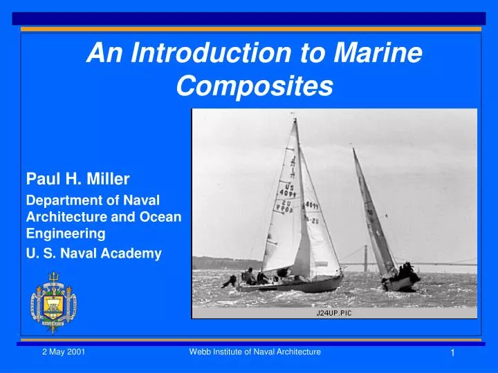
An Introduction to Marine Composites Paul H. Miller Department of Naval Architecture and Ocean Engineering U. S. Naval Academy Webb Institute of Naval Architecture
Why use composites in the marine environment What are they How to analyze them Design Examples IACC rudder 78’ performance cruiser A marine composites dissertation project Presentation Overview Webb Institute of Naval Architecture
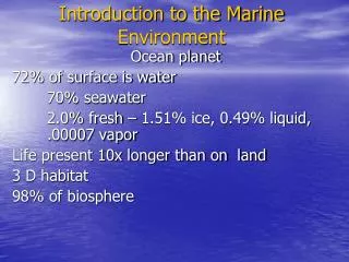
Approximately 1/3 of marine applications are now made of composites Low maintenance requirements (low life-cycle costs) High specific material properties High geometric flexibility Good moisture stability Why Marine Composites? Webb Institute of Naval Architecture
Why not? • High Initial Cost • Tight tolerances required • Fire/smoke toxicity • Environmental Webb Institute of Naval Architecture
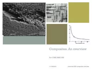
A “Composite” • A combination of more than one material with resulting properties different from the components • Examples: • Reinforced concrete • Wood • Polymer composites (1000+ resins, 25+ fibers, 20+ cores) • Note: a “composite ship” is not a composite material Webb Institute of Naval Architecture
Isotropic Materials (ie metals) E t , c , Transversely Isotropic Materials (ie one fiber in resin) Ex (fiber direction), Ey , Gxy xy xt , xc ,yt , yc ,xy Material Properties Webb Institute of Naval Architecture
Analysis Methods • Classical Lamination Theory – Timoshenko’s layered stiffness/stress approach. Uses matrix algebra. • “Blended Isotropic” – ABS Method • Empirical - Gerr Webb Institute of Naval Architecture
CLT Analytically difficult Accurate to within 1% if base properties are known. Possible unconservative inaccuracy to 15% “Blended Isotropic” Analytically easy Accuracy to within 1% if all properties are known. Possible unconservative inaccuracy to a factor of 4! Methods Compared Webb Institute of Naval Architecture
Suggestions • Use “blended isotropic” for preliminary design (or to check for ABS compliance) only! • Use CLT for all final design! Webb Institute of Naval Architecture
Tensile Test Typical Material Properties • Mostly linear stress/strain • Brittle (0.8-2.7% ultimate strain) resins or fibers • Stiffness and Strength Properties (ASTM tests – Wet/Dry) • Tensile • Compressive • Shear • Flex • Fatigue Webb Institute of Naval Architecture
Moisture Absorption Results 1.8% weight gain for submerged 1.3% for 100% relative humidity Equilibrium in 4 months Webb Institute of Naval Architecture
Example Design Problem – IACC Rudder • Goal: As light as possible without breaking! • Construction: Carbon fiber and epoxy • Loads from Lift equations and CFD Webb Institute of Naval Architecture
Geometry Loads Fwd speed Backing speed Angle of Attacks Preliminary analysis from beam equations/CLT/ lift equation FEA model Laminate tailoring CFD loads Tsai-Wu and Hashin failure criteria Approach Webb Institute of Naval Architecture
77 foot Performance Cruiser • Carl Schumacher design • Building at Timeless Marine, Seattle • To ABS Offshore Yacht Guide Webb Institute of Naval Architecture
Approach • Preliminary design using CLT (“Laminator”), MathCad (for ABS equivalent) and Excel (ABS Guide) • Final design using FEA • Nine load cases • 15% increased in FEA over ABS Webb Institute of Naval Architecture
My Dissertation • Extend the standard fatigue methods used for metal vessels to composite vessels • Verify the new method by testing coupons, panels and full-size vessels. Webb Institute of Naval Architecture
Simplified Metal Ship Fatigue Design • Predict wave encounter ship “history” • Find hull pressures and accelerations using CFD for each condition • Find hull stresses using FEA • Wave pressure and surface elevation • Accelerations • Use Miner’s Rule and S/N data to get fatigue life Webb Institute of Naval Architecture
Project Overview • Material and Application Selection • Testing (Dry, Wet/Dry, Wet) • ASTM Coupons, Panels, Full Size • Static and Fatigue • Analysis • Local/Global FEA • Statistical and Probabilistic Webb Institute of Naval Architecture
Material & Application Selection Ideally they should represent a large fraction of current applications! • Polyester Resin (65%) • E-glass (73%) • Balsa Core (30%) • J/24 Class Sailboat • 5000+ built • Many available locally • Builder support • Small crews Another day of research… Webb Institute of Naval Architecture
Finite Element Analysis • Coupon, panel, global • Element selection • Linear/nonlinear • Static/dynamic/quasi-static • CLT shell • Various shear deformation theories used (Mindlin and DiScuiva) • COSMOS/M software • Material property inputs from coupon tests Webb Institute of Naval Architecture
Fatigue Testing Webb Institute of Naval Architecture
Fatigue Results – S/N Data Moisture decreased initial and final stiffness but the rate of loss was the same. Specimens failed when stiffness dropped 15-25% No stiffness loss for 12.5% of static failure load specimens 25% load specimens showed gradual stiffness loss Webb Institute of Naval Architecture
Panel Analysis • Responds to USCG/SNAME studies • Solves edge-effect problems • Hydromat test system • More expensive • Correlated with FEA Webb Institute of Naval Architecture
Panel FEA Results Webb Institute of Naval Architecture
Impact Testing • The newest boat had the lowest stiffness. • Did the collision cause significant microcracking? Yes, there was significant microcracking! Webb Institute of Naval Architecture
Global FEA • Created from plans and boat checks • Accurately models vessel • 8424 quad shell elements • 7940 nodes • 46728 DOF • Load balance with accelerations Webb Institute of Naval Architecture
On-The-Water Testing- Set Up Webb Institute of Naval Architecture
Wind Strains Accelerations Data Records Webb Institute of Naval Architecture