Download
1 / 23
250 likes | 502 Views
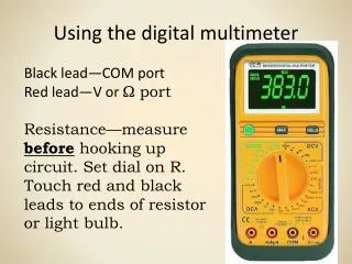
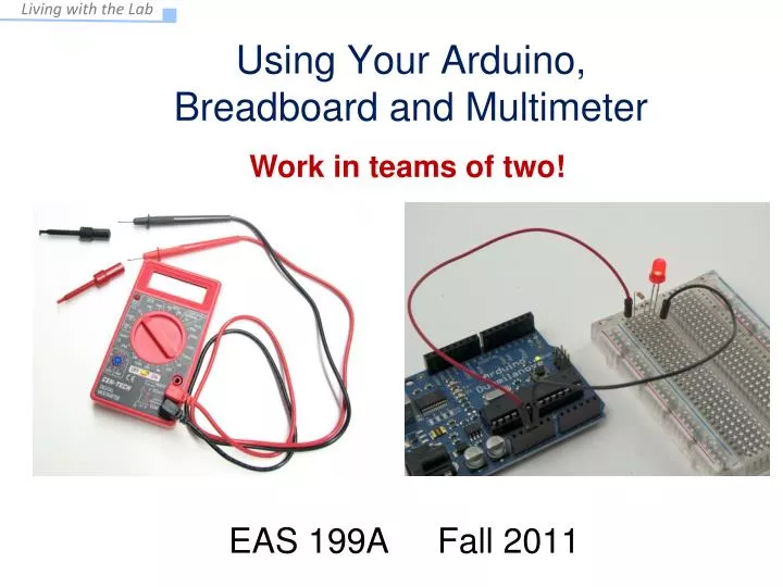
Work in teams of two!. Using Your Arduino, Breadboard and Multimeter. EAS 199A Fall 2011. Your Multimeter. pincer clips – good for working with breadboard wiring. probes. (push these onto probes). leads. T urn knob to select the type of measurement.

E N D
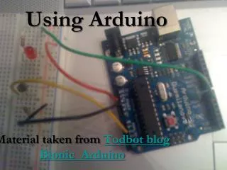
Work in teams of two! Using Your Arduino, Breadboard and Multimeter EAS 199A Fall 2011
Your Multimeter pincer clips – good for working with breadboard wiring probes (push these onto probes) leads Turn knob to select the type of measurement. You will use the multimeter to understand and troubleshoot circuits, mostly measuring DC voltage, resistance and DC current.
The Arduino Duemilanove Duemilanove means “2009” in Italian Power can be provided through the USB cable (+5V from the computer) or externally (7-12V supply recommended)
The Arduino Uno The Arduino Uno was released in September 2010 as an update to the Duemilanove Power can be provided through the USB cable (+5V from the computer) or externally (7-12V supply recommended)
Measure Vin Vin is the voltage of the power supply. The USB supplies a nominal 5V (4.43V was measured when this photo was taken)
Change power source and measure Vin In this photo, a 7V DC power supply was plugged into the power jack of the Arduino.
Check Voltage at 5V Power Pin The on-board voltage regulator maintains the voltage on the 5V pin at about 5V The measured voltage is close to 5V target.
Check Voltage at 3.3V Pin The FIDI chip on the Arduino, which helps the microcontroller talk with your computer through the USB cable, also has an on-board voltage regulator that outputs 3.3V. If you need less than 5V for a project, you can use the 3.3V pin, Which provides about 3.3V. The current draw from the 3V3 pin is limited to 50mA. max power = V∙I = 3.3V∙0.05A = 0.165W = 165mW
Select Resistors Find the 330Wand the 10kW resistors from your parts kit . gold = ±5% silver = ±20% first digit tolerance number of zeros seconddigit Example: 330W resistor: 3 = orange 3 = orange Add 1 zero to 33 to make 330, so 1 = brown So, 330 =orange,orange, brown Now, find the 10kW resistor.
LED circuit: Two equivalent pictures
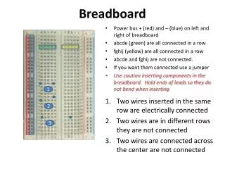
Building an LED Circuit • Supplies: • 2 two jumper wires – colors don’t matter, but red is usually used for positive, and black is used for negative • LED • 330 Ω and 10kΩ resistors • Arduino • Breadboard • USB cable from your computer)
LEDs LED = Light Emitting Diode + - electronic symbol Diagram from Wikipedia description of an LED Electricity can only flow one way through an LED (or any diode). The flat spot on the LED must be connected to ground (GND).
Building an always-on LED Circuit Short leg of LED connects to ground wire
The Circuit These circuit diagrams are equivalent Symbol for ground (GND)
Replace the 330WResistor with the 10kW Resistor What happens and Why?? ANSWER: The smaller resistor (330Ω) provides less resistance to current than the larger resistor (10kW). For the same applied voltage, increasing the resistance decreases the current. Therefore, replacing the 300Ω resistor with the 10kΩ resistor reduces the current and causes the LED to glow less brightly. What would happen if you forgot to put in a resistor? You would probably burn up your LED.
Arduino program to blink an LED • Build the circuit on the breadboard • A slight modification to always-on LED circuit • Write your first Arduino program • Use the digital (on/off) output to turn LED on and off
Connect the Power Wire to Pin 2 (Use P2 as a digital output) Enter and run the following program: void setup() { // initialize pin as an output: pinMode(2, OUTPUT); } void loop() { // turn the LED on digitalWrite(2, HIGH); // wait 1 second = 1000 ms delay(1000); // turn the LED off digitalWrite(2, LOW); // wait for 500 ms delay(500); }
How the Program Works void setup() { pinMode(2, OUTPUT); } void loop() { digitalWrite(2, HIGH); delay(1000); digitalWrite(2, LOW); delay(500); } initialize pin 2 as an output set pin 2 to HIGH (5V) wait 1000 ms infinite loop set pin 2 to LOW (0V) wait 500 ms 1000 ms 500 ms 5V voltage (V) HIGH = 5V and LOW = 0V (Always!!!!) 0V time (ms)
Now Experiment on Your Own! • Try changing the time to 1.5 seconds on and 1 second off • Connect the resistor to digital pin 5 and change the program to match • Blink out SOS in Morse code (dot-dot-dot-dash-dash-dash-dot-dot-dot) • three short pulses (0.25 seconds each) followed by . . . • three long pulses (0.75 second each) followed by . . . • three short pulses (0.25 seconds each) followed by . . . • a brief pause (1 second) • repeat a through d using an infinite loop Show your instructor when you have completed exercise (3)
Find the each command in the reference section of arduino.cc (discuss each command with others at your table) void setup() { // initialize the digital pin as an output: pinMode(2, OUTPUT); } void loop() { digitalWrite(2, HIGH); // set the LED on delay(1000); // wait for a second digitalWrite(2, LOW); // set the LED off delay(500); // wait for 500 ms }