Download
1 / 19
190 likes | 225 Views
% vcs foo.v. Compiles the Verilog into an executable binary. Simulation executable (simv). % simv. Simulates the Verilog by running the executable. Synopsys Tools for Verilog Simulation. VCS - Verilog simulator tool Get manual by using vcs -doc Run GUI by using vcs -RI.

E N D
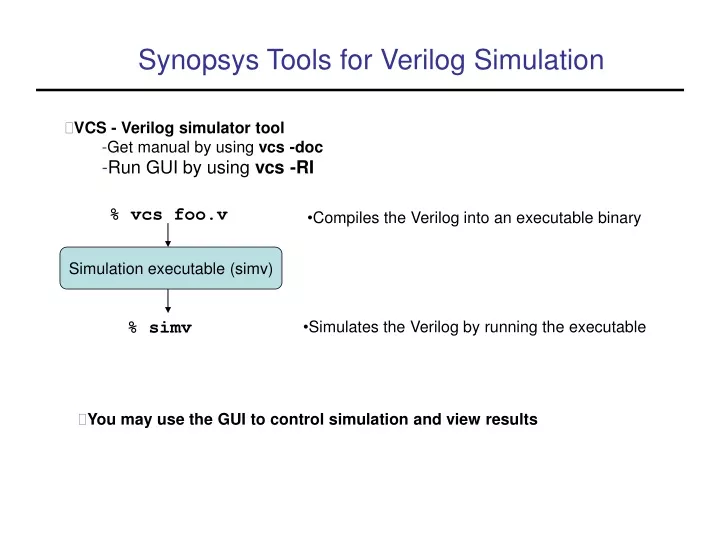
% vcs foo.v • Compiles the Verilog into an executable binary Simulation executable (simv) % simv • Simulates the Verilog by running the executable Synopsys Tools for Verilog Simulation • VCS - Verilog simulator tool • Get manual by using vcs -doc • Run GUI by using vcs -RI • You may use the GUI to control simulation and view results
Setup to Run Synopsys Tools • % module load synopsys/vcs - sets up key environment variables • % module load acroread - needed to run see manual (vcs -doc) • vcs GUI/manual (-RI, -doc) is an X application so: • Run an Xclient on your local machine • Set remote DISPLAY variable to local display • Give CS machine permission to control your DISPLAY • Ask CS support about how to do these things
vcs sig_ctrl.v • simv • Only $display/$monitor statements will appear • There are many compiler and execution options (see vcs manual) • vcs -I sig_ctrl.v • simv • -I option compiles for interactive (debugging) mode • Simulation will occur and you will get a command line interface (CLI) prompt • -RI option compiles for interactive mode and starts GUI • GUI allows you to run simulation and debug • vcs -RI sig_ctrl.v Running a Basic Simulation
Verilog Basics, Modules module T_FF (q, clock, reset); . . . . endmodule • Similar to a class, can be instantiated many times • I/O ports declared at the top • Typically represents a physical component • Can be structurally connected to other components • Cannot be invoked like a function
Levels of Abstraction • Behavioral • Procedural code, similar to C programming • Little structural detail (except module interconnect) • Dataflow • Specifies transfer of data between registers • Some structural information is available (RTL) • Sometimes similar to behavior • Structural (gate,switch) • Interconnection of simple components • Purely structural
Instances module ripple_carry_counter(q, clk, reset); output [3:0] q; input clk, reset; //4 instances of the module TFF are created. TFF tff0(q[0],clk, reset); TFF tff1(q[1],q[0], reset); TFF tff2(q[2],q[1], reset); TFF tff3(q[3],q[2], reset); endmodule module TFF(q, clk, reset); output q; input clk, reset; wire d; DFF dff0(q, d, clk, reset); not n1(d, q); endmodule • TFF is instantated within ripple_carry_counter • DFF and not are instantiated within TFF • Structural interconnect is established through instantiation
Testbench (Stimulus Block) // Control the reset initial begin reset = 1'b1; #15 reset = 1'b0; #180 reset = 1'b1; #10 reset = 1'b0; #20 $stop; end // Monitor the outputs initial $monitor($time, " Output q = %d", q); endmodule module stimulus; reg clk; reg reset; wire[3:0] q; // instantiate the design block ripple_carry_counter r1(q, clk, reset); // Control the clock initial clk = 1'b0; always #5 clk = ~clk; • The testbench generates the input stimulus • Observation of data is often included in the testbench
Data Values and Strengths 0, 1, X, Z • Reflect traditional digital logic values Strengths from highZ -> supply • Used to resolve conflicts between drivers
Nets (Wires) and Registers • Nets represent physical connections between hardware elements • Declared with the keyword wire (or default for ports) • Used to connect instantiated modules • Must be continuously driven with a value • Ex. wire b, c; • Registers represent storage elements • Not necessarily physical registers but synthesis tools often assume that • Registers do not need to be continuously driven • Registers will hold a value until it is overwritten • Ex. • reg reset; • initial • begin • reset = 1’b1; • #100 reset = 1’b0; • end
Vectors • Nets and Registers can be declared as vectors • If no bitwidth is specified, 1 bit is assumed wire [7:0] a; reg [0:31] addr1, addr2; • Subsets of bits can be selected addr1[2:0] = addr2[3:1];
Other Data Types • Verilog allows integers, real, and time types • Arrays can be made from other types • - Arrays can be multidimensional • - A vector is conceptually a single elements with many bits • - An array is many elements put together wire [7:0] x; // a vector wire x [7:0]; // an array wire [7:0] x [7:0]; // an array of vectors wire x[7:0][7:0]; // a two dimensional array • Parameters are constants parameter line_width=80;
System Tasks and Compiler Directives • Typically I/O tasks which require special simulator operations System Tasks: $<keyword>, used at simulation time - $display is a print statement in the code (like printf) $display(“Hello, world!”); - $monitor prints a signal value when it changes $monitor(“clock= %b, reset = %b”, clock, reset); - Only one $monitor statement can be active - $monitoron, $monitoroff Compiler Directives: ‘<keyword>, used at compile time - ‘define creates macros (just like #define in C) ‘define x 32 - ‘include inserts entire verilog files (just like #include in C ‘include header.v
Dataflow Descriptions, Continuous Assignments assign out = i1 & i2; • Use the assign keyword (in most cases) • Left hand side must be a net of some kind (scalar or vector), not a register • Right hand side can be registers, nets, or function calls • Continuous assignments are always active. Execution hard to trace • They are evaluated whenever a right hand side operand changes value • Delays (inertial) can be added to represent component delays assign #10 out = i1 & i2; • Continuous assignment can be implicit in a net declaration wire out = i1 & i2;
Continuous Assignment Example module edge_dff(q, qbar, d, clk, clear); // Inputs and outputs output q,qbar; input d, clk, clear; // Internal variables wire s, sbar, r, rbar,cbar; //Make complement of clear assign cbar = ~clear; // Input latches assign sbar = ~(rbar & s), s = ~(sbar & cbar & ~clk), r = ~(rbar & ~clk & s), rbar = ~(r & cbar & d); // Output latch assign q = ~(s & qbar), qbar = ~(q & r & cbar); endmodule • This is basically a structural description
Behavioral Modeling, Structured Procedures Always blocks and initial blocks - Parallel constructs: all blocks can execute in parallel Initial blocks - The block executes only once - By default, starts at time 0 (but this can be changed) - Often used for initialization module stimulus; reg x,y, a,b, m; initial begin #5 a = 1'b1; #25 b = 1'b0; end initial begin #10 x = 1'b0; #25 y = 1'b1; end endmodule
Always Blocks Always blocks - The block executes in an infinite loop - By default, starts at time 0 (but this can be changed) - Represents a concurrent hardware block - Needs a delay module clock_gen; reg clock; initial clock = 1'b0; always #10 clock = ~clock; initial #1000 $finish; endmodule
Procedural Statements, Blocking Assignments Blocking Assignments - Represented with a = sign - All blocking assignments are executed in sequence module dummy; reg x, y, z; reg [15:0] reg_a, reg_b; integer count; initial begin x = 0; y = 1; z = 1; count = 0; reg_a = 16'b0; reg_b = reg_a; reg_a[2] = #15 1; reg_b[15:13] = #10 {x, y, z}; count = count + 1; end
Non-Blocking Assignments Non-Blocking Assignments - Represented with a <= sign - All non-blocking assignments are executed in parallel - Try not to mix with blocking assignments module dummy; reg x, y, z; reg [15:0] reg_a, reg_b; integer count; initial begin x = 0; y = 1; z = 1; count = 0; reg_a = 16'b0; reg_b = reg_a; reg_a[2] <= #15 1; reg_b[15:13] <= #10 {x, y, z}; count = count + 1; end
Delay and Event Control Delay Statements - Represented with a # sign - Delays the execution of the statement immediately after - Inertial delay model (ignores glitches) - Additive with blocking statements Event Control Statements - Edge sensitive, represented with a @ sign - Delays the execution until expression transitions Ex. always @(clock) always @(posedge clock) always @(a or b)- Level sensitive, represented with wait statement Ex. always wait (enable) #20 cnt = cnt + 1;