Download
1 / 49
910 likes | 1.91k Views
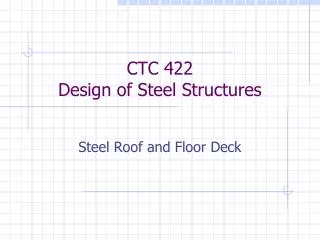
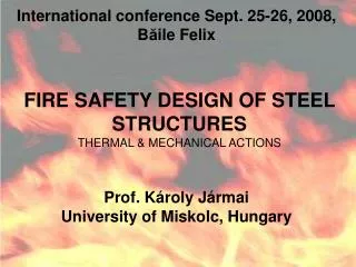
International conference Sept. 25-26, 2008, B ă ile Felix. FIRE SAFETY DESIGN OF STEEL STRUCTURES THERMAL & MECHANICAL ACTIONS. Prof. K ároly Jármai University of Miskolc, Hungary. Resistance to Fire - Chain of Events. Loads. . Steel columns. time. R. time. 1: Ignition.

E N D
International conference Sept. 25-26, 2008, Băile Felix FIRE SAFETY DESIGN OF STEEL STRUCTURES THERMAL & MECHANICAL ACTIONS Prof. Károly Jármai University of Miskolc, Hungary Part 1: Thermal & Mechanical Actions
Resistance to Fire - Chain of Events Loads Steel columns time R time 1: Ignition 2: Thermal action 3: Mechanical actions 4: Thermal response 5: Mechanical response 6: Possible collapse Part 1: Thermal & Mechanical Actions
Thermal action on structure Composite Slab 1 side exposed Column 4 sides exposed Part 1: Thermal & Mechanical Actions
Heat transfer at surface of building elements Net Radiative Heat Flux Net Convective Heat Flux Total net Heat Flux + = & & & h h h net net,c net , r • Exposed side • Non-exposed side Part 1: Thermal & Mechanical Actions
Structural Fire Safety Engineering vs. Classification Prescriptive Performance based Part 1: Thermal & Mechanical Actions
Actions on Structures Exposed to FireEN 1991-1-2 - Prescriptive Rules Design Procedures Prescriptive Rules Performance-Based Code (Thermal Actions given by Nominal Fire) (Physically based Thermal Actions) Part 1: Thermal & Mechanical Actions
Nominal Temperature-Time Curve *) Nominal temperature-time curve Standard temperature-, External fire - & Hydrocarbon fire curve No data needed *) Simplified Fire Models Localised Fire Fully Engulfed Compartment - HESKESTADT Rate of heat release Fire surface Boundary properties Opening area Ceiling height - Parametric Fire - HASEMI q (t) uniform in the compartment q (x, y, z, t) + Exact geometry *) Advanced Fire Models - One-Zone Model - Two-Zone Model - Combined Two-Zones and One-Zone fire - CFD Part 1: Thermal & Mechanical Actions
Prescriptive Fire Regulations Defining ISO Curve Requirements ISO ISO Time [min] ISO ISO ISO ISO ISO ISO ISO-834 Curve (EN1364 -1) T = 20 + 345 log (8 t + 1) q [°C] 1200 1110 1049 1006 The ISO curve * Has to be considered in the WHOLE compartment, even if the compartment is huge 1000 945 842 800 600 400 * Never goes DOWN * does not consider the PRE-FLASHOVER PHASE * Does not depend on FIRE LOAD and VENTILATION CONDITIONS 200 0 90 120 0 30 60 180 Part 1: Thermal & Mechanical Actions
Stages of a Natural Fire and the Standard Fire Curve Post- Flashover 1000-1200°C Pre- Flashover Flashover Temperature Natural fire curve ISO834 standard fire curve Time Heating Ignition - Smouldering Cooling …. Part 1: Thermal & Mechanical Actions
Sprayed Protection Part 1: Thermal & Mechanical Actions
Partially Encased Beams & Columns Part 1: Thermal & Mechanical Actions
Actions on Structures Exposed to FireEN 1991-1-2 - Performance Based Code Design Procedures Prescriptive Rules Performance-Based Code (Physically based Thermal Actions) (Thermal Actions given by Nominal Fire) Part 1: Thermal & Mechanical Actions
Natural Fire Safety Concept ISO curve q [°C] 1200 1000 800 600 400 200 0 30 60 90 120 180 0 Time [min] • Implemented in: • EN 1991-1-2 • Some National Fire Regulations • include now alternative requirements • based on Natural Fire Part 1: Thermal & Mechanical Actions
NFSC Valorisation Project Part 1: Thermal & Mechanical Actions
Natural Fire Model *) Nominal temperature-time curve Standard temperature-, External fire - & Hydrocarbon fire curve No data needed *) Simplified Fire Models Localised Fire Fully Engulfed Compartment - HESKESTADT Rate of heat release Fire surface Boundary properties Opening area Ceiling height - Parametric Fire - HASEMI q (t) uniform in the compartment q (x, y, z, t) + Exact geometry *) Advanced Fire Models - One-Zone Model - Two-Zone Model - Combined Two-Zones and One-Zone fire - CFD Part 1: Thermal & Mechanical Actions
List of needed Physical Parameters for Natural Fire Model • Boundary properties • Ceiling height • Opening Area • Fire surface • Rate of heat release Geometry Fire Part 1: Thermal & Mechanical Actions
Characteristics of the Fire Compartment Fire resistant enclosures defining the fire compartment according to the national regulations Material properties of enclosures: c, r, l Definition of Openings Part 1: Thermal & Mechanical Actions
Characteristic of the Fire for Different Buildings RHR Fire Load q Fire Growth f f,k Occupancy Rate 80% fractile [kW/m²] [MJ/m²] Dwelling Medium 250 948 (room) Hospital Medium 250 280 (room) Hotel Medium 250 377 Library Fast 500 1824 Office Medium 250 511 School Medium 250 347 Shopping Centre Fast 250 730 (movie/cinema) Theatre Fast 500 365 (public space) Transport Slow 250 122 Part 1: Thermal & Mechanical Actions
Fire Load Density 25 1,10 1,50 Examples Danger of Danger of Compartment Fire Activation Fire Activation of floor area Af [m²] q2 q1 Occupancies Art gallery, museum, 0,78 swimming pool 1,00 250 Residence, hotel, office Manufactory for machinery 1,22 2500 1,90 & engines Chemical laboratory, 1,44 5000 2,00 Painting workshop Manufactory of fireworks 2,13 1,66 10000 or paints ni Function of Active Fire Safety Measures Automatic Fire Suppression Automatic Fire Detection Manual Fire Suppression Automatic fire Automatic Automatic Independent Work Safe Fire Smoke Off Site Alarm Detection Water Water Fire Fire Access Fighting Exhaust Transmission & Alarm Supplies Extinguishing Brigade Brigade Routes Devices System to by by System Fire Brigade 0 1 2 Heat Smoke n1 n5 n6 n7 n8 n9 n10 n2 n3 n4 0,9 or 1 1,0 1,0 0,61 or 0,78 0,61 0,87 or 0,73 0,87 1,0 0,87 0,7 1,5 1,5 1,5 Part 1: Thermal & Mechanical Actions
Growing phase Rate of Heat Release CurveStationary State and Decay Phase 10 Ultra- Fast (FGR) Fast (FGR) 9 8 Medium (FGR) 7 10 Steady state 6 RHR [MW] 9 Fire Growth Rate = FGR A x RHR f f 5 8 COMPARTMENT FIRE 4 Slow (FGR) 7 3 6 2 300'' 75'' 150'' 600'' 5 RHR [MW] 1 t [min] 4 A x RHR f f 0 0 5 10 15 20 3 Ventilation Controlled Fire 2 Decay phase 1 Decay Phase t [min] 0 70% (qf,d • Afi) 0 5 10 15 20 25 30 tdecay RHR [MW] 0 Time [min] Part 1: Thermal & Mechanical Actions
Natural Simplified Fire Model *) Nominal temperature-time curve Standard temperature-, External fire - & Hydrocarbon fire curve No data needed *) Simplified Fire Models Localised Fire Fully Engulfed Compartment - HESKESTADT Rate of heat release Fire surface Boundary properties Opening area Ceiling height - Parametric Fire - HASEMI q (t) uniform in the compartment q (x, y, z, t) + Exact geometry *) Advanced Fire Models - One-Zone Model - Two-Zone Model - Combined Two-Zones and One-Zone fire - CFD Part 1: Thermal & Mechanical Actions
Simplified Fire ModelsLocalised Fire FULLY ENGULFED COMPARTMENT LOCALISED FIRE q (t) uniform in the compartment q (x, y, z, t) Part 1: Thermal & Mechanical Actions
Real Localised Fire Test Part 1: Thermal & Mechanical Actions
Localised Fire: HESKESTAD Method • Annex C of EN 1991-1-2: • Flame is not impacting the ceiling of a compartment (Lf < H) • Fires in open air Q(z) = 20 + 0,25 (0,8 Qc)2/3 (z-z0)-5/3 900°C Flame axis The flame length Lf of a localised fire is given by : Lf = -1,02 D + 0,0148 Q2/5 H L f z D Part 1: Thermal & Mechanical Actions
Localised Fire: HASEMI Method • Annex C of EN 1991-1-2: • Flame is impacting the ceiling (Lf> H) concrete slab beam q g Y = Height of the free zone q = Air Temperature Calculated by CaPaFi at Beam Level x Part 1: Thermal & Mechanical Actions
Simplified Fire ModelsFully Engulfed Compartment FULLY ENGULFED COMPARTMENT LOCALISED FIRE q (t) uniform in the compartment q (x, y, z, t) Part 1: Thermal & Mechanical Actions
Real Fire Test Simulating an Office Building Fully engulfed fire Part 1: Thermal & Mechanical Actions
Fully Engulfed Compartment Parametric Fire Temperature [°C] Annex A of EN 1991-1-2 For a given b, qfd, At & Af Part 1: Thermal & Mechanical Actions
Natural Advanced Fire Model *) Nominal temperature-time curve Standard temperature-, External fire - & Hydrocarbon fire curve No data needed *) Simplified Fire Models Localised Fire Fully Engulfed Compartment - HESKESTADT Rate of heat release Fire surface Boundary properties Opening area Ceiling height - Parametric Fire - HASEMI q (t) uniform in the compartment q (x, y, z, t) + Exact geometry *) Advanced Fire Models - One-Zone Model - Two-Zone Model - Combined Two-Zones and One-Zone fire - CFD Part 1: Thermal & Mechanical Actions
Advanced fire Models LOCALISED FIRE The Fire switch to a fully engulfed fire The Fire stays localised LOCALISED FIRE FULLY ENGULFED COMPARTMENT Part 1: Thermal & Mechanical Actions
Large Compartment Test Fire Load Part 1: Thermal & Mechanical Actions
Large Compartment Test External Flaming During the Test Part 1: Thermal & Mechanical Actions
Large Compartment Test After the Test Part 1: Thermal & Mechanical Actions
Two Zone Calculation Software “OZone V2.2” Part 1: Thermal & Mechanical Actions
OZone results: Input and Computed RHR Part 1: Thermal & Mechanical Actions
OZone results: Gas Temperatures θHot θCold Part 1: Thermal & Mechanical Actions
OZone results: Smoke Layer Thickness Part 1: Thermal & Mechanical Actions
Calibration of Software OZone: Gas Temp 1400 1200 1000 800 600 400 200 0 0 200 400 600 800 1000 1200 MAXIMUM AIR T EMPERATURE OZone OZone [°C] MAXIMUM AIR T EMPERATURE IN THE COMPARTMENT 1400 TEST [°C] Part 1: Thermal & Mechanical Actions
Calibration of Software OZone: Steel Temp 1400 UNPROTECTED STEEL TEMPERATURE 1200 1000 800 OZone [°C] 600 400 200 0 0 200 400 600 800 1000 1200 1400 TEST [°C] Part 1: Thermal & Mechanical Actions
OZone: Case Study Influence of the Actives Fire Safety Measures 1000 Office : A = 291,2 m² f O.F. = 0,04 m½ ; Fire Load q = 511 MJ/m² 900 f,k No Fire Active Measures 800 Off Site Fire Brigade 700 Automatic Fire Detection & Alarm by Smoke 600 Automatic Alarm Transmission to Fire Brigade 500 Automatic Water Extinguishing System Gas temperature [°C] 400 Design Fire Load q [ MJ/m² ] 625 356 310 189 f,d 300 200 Õ d d d m q = q 100 f , d ni f , k q1 q2 i 0 0 10 20 30 40 50 60 70 80 90 100 110 120 130 140 150 Time [min] Part 1: Thermal & Mechanical Actions
Computer Fluid Dynamics: Software Sofie Grid definition Part 1: Thermal & Mechanical Actions
Sofie Results: Gas Temperatures Part 1: Thermal & Mechanical Actions
Resistance to Fire - Chain of Events Loads Steel columns time R time 1: Ignition 2: Thermal action 3: Mechanical actions 4: Thermal response 5: Mechanical response 6: Possible collapse Part 1: Thermal & Mechanical Actions
Basis of Design and Actions on Structures S Actions for temperature analysis W Thermal Action G A FIRE C T I Actions for structural analysis Q O Mechanical Action N Dead Load G S Imposed Load Q Snow S Wind W Fire Part 1: Thermal & Mechanical Actions
Combination Rules for Mechanical ActionsEN 1990: Basis of Structural Design Room temperature + + y E G å Q Q = d G Q,1 1 0,i Q,i i i >1 f.i. : Offices area with the imposed load Q, the leading variable action = 1,35 G + 1,5 Q + 0,6 • 1,5 W + 0,5 • 1,5 S E d Part 1: Thermal & Mechanical Actions
Combination Rules for Mechanical ActionsEN 1990: Basis of Structural Design E = G + 0,5 Q fi,d E = G + 0,2 W + 0,3 Q fi,d Fire conditions Accidental situation = + y + y å E G Q Q i 1 fi,d 1or2,i 1or2,1 i >1 f.i. : Offices area with the imposed load Q, the leading variable action Offices area with the wind W, the leading variable action Part 1: Thermal & Mechanical Actions
Values of factors for buildings y y y Action 1 2 0 Imposed loads in buildings, category (see EN 1991-1.1) Category A : domestic, residential areas 0,7 0,5 0,3 0,3 Category B : office areas 0,7 0,5 Category C : congregation areas 0,7 0,7 0,6 0,6 Category D : shopping areas 0,7 0,7 Category E : storage areas 1,0 0,9 0,8 Category F : traffic area vehicle weight £ 30kN 0,7 0,7 0,6 Category G : traffic area, 0,3 30 kN < vehicle weight £ 160kN 0,7 0,5 0 Category H : roofs 0 0 Snow loads on buildings (see EN1991-1.3) Finland, Iceland, Norway, Sweden 0,70 0,50 0,20 Remainder of CEN Member States, for sites located at altitude 0,70 0,50 0,20 H > 1000 m a.s.l. Remainder of CEN Member States, for sites located at altitude 0,50 0,20 0 £ H 1000 m a.s.l. Wind loads on buildings (see EN1991-1.4) 0,6 0,2 0 Temperature (non-fire) in buildings (see EN1991-1.5) 0,6 0,5 0 ( Reference : EN1990 - February 2002) Part 1: Thermal & Mechanical Actions
Load Factor Maximal Load level after R30 Part 1: Thermal & Mechanical Actions