Download
1 / 27
270 likes | 418 Views
LCLS Bunch Length Monitor Conceptual Design Review Instrument Design Considerations February 23, 2006. LCLS Bunch length monitor system:. Two subsystems: Deflecting structure ‘LOLA’ Accurate, calibrated, complex Destructive – ‘pulse stealing mode ok’ Expensive Tested Radiation monitors

E N D
LCLS Bunch Length Monitor Conceptual Design Review Instrument Design ConsiderationsFebruary 23, 2006 LCLS Bunch Length Monitor Marc Ross - SLAC
LCLS Bunch length monitor system: • Two subsystems: • Deflecting structure ‘LOLA’ • Accurate, calibrated, complex • Destructive – ‘pulse stealing mode ok’ • Expensive • Tested • Radiation monitors • Dipole radiation • Gap radiation • Simple sensors • Cheap • Tested Complementary devices LCLS Bunch Length Monitor Marc Ross - SLAC
Bunch length monitor system Dipole radiation Gap radiation LOLA Video signal mm wave optics WG Pyro-electric detector High frequency diode Single signal device LCLS Bunch Length Monitor Marc Ross - SLAC
Two coherent radiation monitors for BC1 • Simple ceramic gap surrounded by mm-wave diode detectors (paired) • Total radiated energy is 2 uJ • For 1nC, 200 micron bunch. • (energy scales as Q^2/(bunch length) • Tested at SLC and ESA (actually many years…) • Annular reflector directs dipole radiation onto mm-wave ‘optics’ – pyroelectric detector • similar total radiated energy • Tested at FFTB/SPPS LCLS Bunch Length Monitor Marc Ross - SLAC
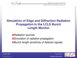
Bunch charge distribution Simple indicator: central frequency of radiated energy
Coherent radiation detection strategy: • Each individual detector has ~ factor 2 range • Long bunches: use diode sequence • (100, 200, 400, 1000 GHz) • Down to 100 um rms • Short bunches: use reflector and pyro-electric detectors • Below 150 um rms • RD required to match – see 2007 testing plan LCLS Bunch Length Monitor Marc Ross - SLAC
ESA 100 GHz Gap and Detector gap LCLS Bunch Length Monitor Marc Ross - SLAC
ESA gap monitor and detector gap • Gap / horn / WG-10 closeup
400 GHz diode LCLS Bunch Length Monitor Marc Ross - SLAC
ESA 100 GHz System – Jan 8, 2006 Sig_z_min ~300 um gap
1nC / 200 um example (Total radiated energy 2uJ) “Energy in” assumes catalog item waveguide horn Detector sensitivity is 2.3e-15J into 50 Ohm out. Good S/N for 100, 200, 400… 1000GHz ? gap Multi-frequency diode ‘xylophone’ LCLS Bunch Length Monitor Marc Ross - SLAC
gap ‘Beam view’ of multi-diode / waveguide assembly LCLS Bunch Length Monitor Marc Ross - SLAC
Reflector • (in use at FFTB for plasma wake exp. – Hogan) • Thin Ti foil ‘in the beam’ – polished. • Si window • Simple, direct, detector optics • Typically shorter than LCLS BC1 (not BC2) • LCLS annular reflector will be 30mm diameter with 14 mm aperture • Capture 50% ~ 1 uJ – at best • Low frequency performance reported to be poor (<300 GHz) LCLS Bunch Length Monitor Marc Ross - SLAC
Alignment Laser 1 µm Titanium Foil at 45º e- 12.5 µm Mylar 1mm HDPE Vacuum Window (3/4” dia) Reference Pyro Detector 12.5 µm Mylar Beam Splitters RT≈0.17 Variable Position Mirror ∆z Interferometer Pyro Detector CTR MICHELSON INTERFEROMETER sx=60 µm, sy=170 µm N≈1.91010 e- • Interference signal normalized to the reference signal • Motion resolution ∆zmin=1 µm or ≈14 fs (round trip) • Mylar: R≈22%, T≈78%, RT≈0.17 reflector
reflector CTR Energy Correlates with Bunch Length Relative Energy @ end of linac
reflector Pyro Is Not The Whole Story Need to Look at Details of the Spectra Example: Jitter from North Damping Ring: X-ray Relative Energy [GeV] • Pyro amplitude is ambiguous • Energy spectra are not • They are complimentary diagnostics • Clear correlation between energy spectrum and E-164X outcome
reflector pyro jitter distribution – SLC NRTL stability
reflector Spectra vs pyro-electric signal
reflector One pyro vs another • meets 5 to 10% resolution goal
reflector Pyro for one band vs another • Pyro response as a function of linac ‘chirp’ (phase - offset)
reflector pyro response has position correlations:
MM Wave detector Sensitivity • Pyroelectric: Basically a charge source, approximately 1.5uC/Joule. • Capacitance is 120pf for 3mm detector. • Charge amplifier (AmpTek A250, external FET), has noise 300 electrons RMS. • Corresponds to 30pJ of mm wave energy • Typically pyro detectors are supplied with included amplifier, performance tends to be worse. • Detector is a thermal integrator. Dynamic range is limited by the dynamic range of the amplifier. • For the AmpTek A250, this is approximately 60,000:1. • Commercial pyroelectric detectors (Scientech PHF02) have noise level of 3nJ, approx 100uJ maximum signal. • Note, sensitivity is 100X worse than theoretical, dynamic range is 30,000:1 LCLS Bunch Length Monitor Marc Ross - SLAC
MM wave diode detectors • Sensitivity of ~2V/W (into 50 Ohms) with ~100GHz bandwidth (at 300GHz). • For a 100ps pulse, Bandwidth ~5GHz. • Noise is 2.3e-15J. • Diodes typically linear to ~30mV output. • 1.5pJ. Dynamic range 700:1 • Expect realistic amplifier (10dB noise figure) to limit dynamic range to 250:1 • Waveguide for 300GHz is WR-2.8, 0.7X0.35mm. • expected attenuation 0.2dB/cm. • Waveguide for 900MHz is WR-1.0, 0.25X0.13mm. • Expected attenuation 1.1dB/cm • Need something like 20cm of waveguide for dispersion • The initial pulse is very short, with extremely high peak power. Waveguide dispersion spreads the pulse in time, while keeping the original frequency content. LCLS Bunch Length Monitor Marc Ross - SLAC
Comparison of pyro and diode detectors • Pyro detectors have much larger dynamic range (>30,000:1, vs ~200:1). • Noise energy diodes is 10^4 lower than for pyro detectors • Pyro area (for sample detector) is ~10 mm^2. • Diode (waveguide) • At 300GHz 0.2mm^2 • At 900GHz 0.03mm^2 • Diode Sensitivity / Area is 250x at 300GHz, 30X at 900GHz • Not clear how much gain available from horn antenna. (~10dB?) • Diodes more sensitive than pyros at 300GHz. • At 900GHz, diodes probably slightly less sensitive. • Dynamic range of pyro detectors is better • Diode alignment of waveguide is much easier. LCLS Bunch Length Monitor Marc Ross - SLAC
Controls and data acquisition • These systems are ‘single signal’ systems, i.e. only a simple gated digitizer is needed* • (Some concerns over gating precision and noise – to be tested) • BC1 Feedback will require beam intensity normalization and (possibly) steering correction / feedback • integration with LOLA improves the systematics greatly we strongly recommend an aggressive approach to LOLA data acq./integration. • Pyro/diode systematics will be different and may require different procedures. • 2007 testing plan LCLS Bunch Length Monitor Marc Ross - SLAC
Testing plan • ESA • Minimum bunch length ~200 um ? • Multi-channel resolution test • No independent high accuracy reference • April and July 2006 • LCLS injector • Minimum bunch length ~ 50 um • High accuracy reference (29-4 LOLA Transverse cavity LCLS Bunch Length Monitor Marc Ross - SLAC