Download
1 / 73
730 likes | 744 Views
Manufacturing Processes. Chapter 6: Sheet Metal Working. Dr. Yazan Al-Zain Department of Industrial Engineering University of Jordan, Amman-Jordan. Introduction. Sheet Metalworking includes cutting and forming operations performed on relatively thin sheets of metal.

E N D
Manufacturing Processes Chapter 6: Sheet Metal Working Dr. Yazan Al-Zain Department of Industrial Engineering University of Jordan, Amman-Jordan
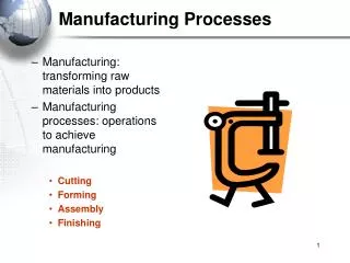
Introduction • Sheet Metalworking includes cutting and forming operations performed on relatively thin sheets of metal. • Typical sheet-metal thicknesses are between 0.4 mm and 6 mm. • For thickness more than 6 mm, the stock is usually referred to as plate rather than sheet. • The sheet or plate stock used in sheet metalworking is produced by flat rolling. • The most commonly used sheet metal is low carbon steel (0.06%–0.15% C). Its low cost and good formability, combined with sufficient strength for most product applications, make it ideal as a starting material.
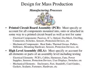
Introduction • Products that include sheet or plate metal parts: automobile and truck bodies, airplanes, railway cars, locomotives, farm and construction equipment, appliances, office furniture, and more. • Accordingly, the commercial importance of sheet metalworking is significant. • Sheet metal parts are generally characterized by high strength, good dimensional accuracy, good surface finish, and relatively low cost. • Economical mass-production: designed to process the parts. Aluminum beverage cans are a prime example.
Introduction • Sheet-metal processing is usually performed at room temperature (cold working). • The exceptions are when the stock is thick, the metal is brittle, or the deformation is significant. These are usually cases of warm working rather than hot working. • Stamping Presses: machine tools on which most sheet-metal operations are performed. • A Punch-and-Die (Stamping Die): the tooling that performs sheet metalwork. • Stampings: the sheet-metal products.
Cutting Operations • Cutting of sheet metal is accomplished by a shearing action between two sharp cutting edges. Figure 20.1 Shearing of sheet metal between two cutting edges: (1) just before the punch contacts work; (2) punch begins to push into work, causing plastic deformation; (3) punch compresses and penetrates into work causing a smooth cut surface; and (4) fracture is initiated at the opposing cutting edges that separate the sheet. Symbols v and F indicate motion and applied force, respectively, t = stock thickness, c = clearance.
Cutting OperationsShearing, Blanking & Punching • The three most important operations in pressworking that cut metal by the shearing mechanism: Shearing, Blanking, and Punching. • Shearing: a sheet-metal cutting operation along a straight line between two cutting edges. • Used to cut large sheets into smaller sections for subsequent pressworking operations. • Performed on a machine called a power shears, or squaring shears. • The upper blade of the power shears is often inclined to reduce the required cutting force.
Cutting OperationsShearing, Blanking & Punching • Shearing: Figure 20.2 Shearing operation: (a) side view of the shearing operation; (b) front view of power shears equipped with inclined upper cutting blade.
Cutting OperationsShearing, Blanking & Punching • The three most important operations in pressworking that cut metal by the shearing mechanism: Shearing, Blanking, and Punching. • Blanking: involves cutting of the sheet metal along a closed outline in a single step to separate the piece from the surrounding stock. • The part that is cut out is the desired product in the operation and is called the blank. • Punching: similar to blanking except that it produces a hole, and the separated piece is scrap, called the slug. • The remaining stock is the desired part.
Cutting OperationsShearing, Blanking & Punching • Blanking and Punching: Figure 20.3 (a) Blanking and (b) punching.
Cutting OperationsEngineering Analysis of Sheet-Metal Cutting • Process parameters in sheet-metal cutting are: • Clearance between punch and die. • Stock thickness. • Type of metal and its strength. • Length of the cut.
Cutting OperationsEngineering Analysis of Sheet-Metal Cutting • Clearance: The clearance c in a shearing operation is the distance between the punch and die, as shown in Figure 20.1(1). • Usually range between 4% and 8% of the sheet-metal thickness. • Improper clearance: see Figure below. Figure 20.4 Effect of clearance: (a) clearance too small causes less than optimal fracture and excessive forces; and (b) clearance too large causes oversized burr (a sharp corner on the edge caused by elongation of the metal during final separation of the two pieces).
Cutting OperationsEngineering Analysis of Sheet-Metal Cutting • Clearance: correct value depends on sheet metal type and thickness. • Allowance depends on the sheet-metal type. • These calculated clearance values can be applied to conventional blanking and hole punching operations to determine the proper punch and die sizes. where c = clearance, mm; a = allowance; and t = thickness, mm.
Cutting OperationsEngineering Analysis of Sheet-Metal Cutting • Whether to add the clearance value to the die size or subtract it from the punch size depends on whether the part being cut out is a blank or a slug, as illustrated below for a circular part. Punch and dies sizes for a round blank of diameter Db: Blanking punch diameter = Blanking die diameter = Punch and dies sizes for a round hole of diameter Dh: Hole punch diameter = Hole die diameter = Figure 20.5 Die size determines blank size Db; punch size determines hole size Dh.
Cutting OperationsEngineering Analysis of Sheet-Metal Cutting • In order for the slug or blank to drop through the die, the die opening must have an angular clearance of 0.25º to 1.5º on each side. Figure 20.6 Angular clearance.
Cutting OperationsEngineering Analysis of Sheet-Metal Cutting • Cutting Forces: important as they determine the size of the press needed. • In case the shear strength was unknown, then: • Example 20.1: where F = cutting force (N); S = shear strength of the metal (MPa); t = stock thickness (mm); and L = length of the cut edge (mm). where TS = ultimate tensile strength (MPa).
Cutting OperationsOther Sheet-Metal-Cutting Operations • In addition to shearing, blanking, and punching, there are several other cutting operations in pressworking. • Cutoff and Parting. • Slotting, Perforating, and Notching. • Trimming, Shaving, and Fine Blanking.
Cutting OperationsOther Sheet-Metal-Cutting Operations • Cutoff and Parting. Figure 20.7 (a) Cutoff and (b) parting. No scrap Scrap forms
Cutting OperationsOther Sheet-Metal-Cutting Operations • Slotting, Perforating, and Notching. Figure 20.8 (a) Slotting (cutting out elongated or rectangular hole), (b) perforating (simultaneous punching of a pattern of holes), (c) notching (cutting out a portion of metal from the side of the sheet) and seminotching (removes a portion of metal from the interior of the sheet).
Cutting OperationsOther Sheet-Metal-Cutting Operations • Trimming, Shaving, and FineBlanking. Figure 20.9 (a) Shaving (to cut unsmooth edges and get accurate dimensions) and (b) fine blanking (gives close tolerance and smooth, straight edges).
Bending Operations • Bending in sheet-metalwork: the straining of the metal around a straight axis. • During the bending: the metal on the inside of the neutral plane is compressed, while the metal on the outside is stretched. • The metal is plastically deformed so that the bend takes a permanent set upon removal of the stresses that caused it. • Bending produces little or no change in the thickness of the sheet metal.
Bending Operations Figure 20.10 (a) Bending of sheet metal; (b) both compression and tensile elongation of the metal occur in bending.
Bending OperationsV-Bending & Edge-Bending • Bending operations are performed using punch and die tooling. • The two common bending methods and associated tooling are V-bending, performed with a V-die; and edge-bending, performed with a wiping die. Figure 20.11 Two common bending methods: (a) V-bending and (b) edge-bending; (1) before and (2) after bending. v = motion, F = applied bending force, Fh = blank.
Bending OperationsV-Bending & Edge-Bending • V-Bending: the sheet metal is bent between a V-shaped punch and die. • Angles ranging from very obtuse to very acute can be made with V-dies. • Generally used for low-production operations. • V-dies are relatively simple and inexpensive. • Edge-Bending: involves cantilever loading of the sheet metal. • A pressure pad is used to apply a force Fh to hold the base of the part against the die, while the punch forces the part to yield and bend over the edge of the die. • Because of the pressure pad, wiping dies are more complicated and costly than V-dies and are generally used for high-production work.
Bending OperationsEngineering Analysis of Bending [1] Metal of thickness t is bent through an angle called the bend angle . [2] Result: a sheet-metal part with an included angle ′, where + ′= 180º. [3] Bend radius (R): specified on the inside of the part, and is determined by the radius on the tooling used to perform the operation. [4] The bend is made over the width of the workpiece w. Figure 20.12 (a) Bending of sheet metal.
Bending OperationsEngineering Analysis of Bending • Bend Allowance: If the bend radius is small relative to stock thickness, the metal tends to stretch during bending. • It is important to be able to estimate the amount of stretching, so that the final part length will match the specified dimension. • The problem is to determine the length of the neutral axis before bending to account for stretching of the final bent section. • This length is called the bend allowance. where Ab = Bend allowance, mm; = bend angle, degrees; R = bend radius, mm; t = stock thickness, mm; and Kba is factor to estimate stretching. values recommended for Kba: if R <2t, Kba = 0.33; and if R> 2t, Kba = 0.50. The values of Kba predict that stretching occurs only if bend radius is small relative to sheet thickness.
Bending OperationsEngineering Analysis of Bending • Spring Back: when the bending pressure is removed at the end of the deformation operation, elastic energy remains in the bent part, causing it to recover partially toward its original shape. • This elastic recovery is called springback. • It is the increase in included angle of the bent part relative to the included angle of the forming tool after the tool is removed. where SB = springback; ’ = included angle of the sheet-metal part, degrees; and ’t= included angle of the bending tool, degrees. Although not as obvious, an increase in the bend radius also occurs due to elastic recovery. The amount of springback increases with modulus of elasticity E and yield strength Y of the work metal.
Bending OperationsEngineering Analysis of Bending • Amount of springback can be compensated by: • Overbending: the punch angle and radius are fabricated slightly smaller than the specified angle on the final part so that the sheet metal springs back to the desired value. • Bottoming: squeezing the part at the end of the stroke, thus plastically deforming it in the bend region. Figure 20.13 Springback in bending shows itself as a decrease in bend angle and an increase in bend radius: (1) during the operation, the work is forced to take the radius Rt and included angle ’t is determined by the bending tool (punch in V-bending); (2) after the punch is removed, the work springs back to radius R and included angle ’.
Bending OperationsEngineering Analysis of Bending • Bending Force: force required to perform bending depends on geometry of the punch-and-die and strength, thickness, and length of the sheet metal. Figure 20.14 Die opening dimension D: (a) V-die, (b) wiping die. This equation is based on bending of a simple beam in mechanics, and Kbf is a constant that accounts for differences encountered in an actual bending process. Its value depends on type of bending: for V-bending, Kbf = 1.33; and for edge bending, Kbf = 0.33. where F = bending force, N; (TS) = tensile strength of the sheet metal, MPa; w = width of part in the direction of the bend axis, mm; t = stock thickness, mm; and D = die opening dimension as defined in Figure 20.12, mm.
Bending OperationsOther Bending & Forming Operations • Flanging: a bending operation in which the edge of a sheet-metal part is bent at a 90º angle (usually) to form a rim or flange. • Often used to strengthen or stiffen sheet metal. • The flange can be formed over a straight bend axis. • It may also involve some stretching or shrinking of the metal. • Hemming: involves cantilever loading of the sheet metal. • Bending edge of the sheet over on itself, in more than one bending step. • Often done to eliminate the sharp edge on the piece, to increase stiffness, and to improve appearance.
Bending OperationsOther Bending & Forming Operations • Seaming: a related operation in which two sheet-metal edges are assembled. • Curling (beading): forms the edges of the part into a roll or curl. • Done for purposes of safety, strength, and aesthetics. • Applications include hinges, pots and pans.
Bending OperationsOther Bending & Forming Operations Figure 20.15 Flanging: (a) straight flanging, (b) stretch flanging, and (c) shrink flanging. Figure 20.16 (a) Hemming, (b) seaming, and (c) curling.
Drawing • Drawing: a sheet metal forming to make cup‑shaped, box‑shaped, or other complex‑curved, hollow‑shaped parts . • Performed by placing a piece of sheet metal over a die cavity and then pushing the metal into the opening with a punch. • The blank must usually be held down flat against the die by a blankholder. • Examples on parts made by drawing: beverage cans, cooking pots, and automobile body panels.
Drawing Figure 20.17 (a) Drawing of a cupshaped part: (1) start of operation before punch contacts work, and (2) near end of stroke; and (b) corresponding workpart: (1) starting blank, and (2) drawn part. Symbols: c = clearance, Db = Blank diameter, Dp = Punch diameter, Rd = die corner radius, Rp = punch corner radius, F = drawing force, Fh = holding force.
DrawingMechanics of Drawing • A blank of diameter Db is drawn into a die cavity by means of a punch with diameter Dp. • The punch and die must have corner radii, given by Rp and Rd. • If the punch and die were to have sharp corners (Rp and Rd = 0), a hole-punching operation would be accomplished rather than a drawing operation. • The sides of the punch and die are separated by a clearance c. This clearance in drawing is about 10% greater than the stock thickness: • The punch applies a downward force F to accomplish the deformation of the metal, and a downward holding force Fh is applied by the blankholder.
DrawingMechanics of Drawing • As the punch proceeds downward toward its final bottom position, the work experiences a complex sequence of stresses and strains as it is gradually formed into the shape defined by the punch and die cavity, as shown below: Figure 20.18 Stages in deformation of the work in deep drawing: (1) punch makes initial contact with work, (2) bending, (3) straightening, (4) friction and compression, and (5) final cup shape showing effects of thinning in the cup walls.
DrawingMechanics of Drawing 1. As the punch first begins to push into the work, the metal is subjected to a bending operation. The sheet is simply bent over the corner of the punch and the corner of the die. The outside perimeter of the blank moves in toward the center in this first stage, but only slightly. 2. As the punch moves further down, a straightening action occurs in the metal that was previously bent over the die radius. The metal at the bottom of the cup, as well as along the punch radius, has been moved downward with the punch, but the metal that was bent over the die radius must now be straightened in order to be pulled into the clearance to form the wall of the cylinder. At the same time, more metal must be added to replace that being used in the cylinder wall. This new metal comes from the outside edge of the blank. This type of metal flow through a constricted space gives the drawing process its name.
DrawingMechanics of Drawing 3. During this stage of the process, friction and compression play important roles in the flange of the blank. In order for the material in the flange to move toward the die opening, friction between the sheet metal and the surfaces of the blankholder and the die must be overcome. (use of lubricants to reduce friction) 4. In addition to friction, compression is also occurring in the outer edge of the blank. As the metal in this portion of the blank is drawn toward the center, the outer perimeter becomes smaller. Because the volume of metal remains constant, the metal is squeezed and becomes thicker as the perimeter is reduced. This often results in wrinkling of the remaining flange of the blank, especially when thin sheet metal is drawn, or when the blankholder force is too low. If the blankholder force is too large, it will prevent the flow resulting in possible tearing of the metal.
DrawingEngineering Analysis of Drawing • Measure of Drawing: • Drawing can be characterized in 3 different ways; Drawing Ratio (DR=Db/Dp), Reduction (r=(Db-Dp)/Db), and Thickness-to-Diameter Ratio (t/Db). • DR should be equal to or less than 2, while r should be less than 0.5. • The greater the ratio, the more severe the drawing. • The t/Db is desirable to be greater than 1% (to avoid wrinkling).
DrawingEngineering Analysis of Drawing • Force: the drawing force required to perform a given operation can be estimated roughly by: • Holding force, expressed by: where F = drawing force, N; t = original blank thickness, mm; TS = tensile strength, MPa; and Db and Dp are the starting blank diameter and punch diameter, respectively, mm. The constant 0.7 is a correction factor to account for friction. where F = holding force, N; Y = yield strength of the sheet metal, MPa; t = starting stock thickness, mm; Rd = die corner radius, mm. The holding force is usually about 1/3 of the drawing force.
DrawingEngineering Analysis of Drawing • Blank Size Determination: for the final dimensions to be achieved on the cylindrical drawn shape, the correct starting blank diameter is needed. • Must be large enough to supply sufficient metal to complete the cup. • Yet if there is too much material, unnecessary waste will result. • The blank diameter can be calculated by setting the initial blank volume equal to the final volume of the product and solving for diameter Db.
DrawingOther Drawing Operations • Redrawing: drawing done in more than a step, in case shape change is too severe. The second drawing step, and any further drawing steps if needed, are referred to as redrawing. Figure 20.19 Redrawing of a cup: (1) start of redraw, and (2)endof stroke.
DrawingOther Drawing Operations • Redrawing: drawing done in more than a step, in case shape change is too severe. The second drawing step, and any further drawing steps if needed, are referred to as redrawing. • First draw: max. reduction 40 to 45%. Second: 30%. Third: 16%. Figure 20.20 Redrawing of a cup: (1) start of redraw, and (2) end of stroke.
DrawingOther Drawing Operations • Drawing of Shapes Other Than Cylindrical Cups: square or rectangular boxes (as in sinks), cups with spherical rather than flat bases, and irregular curved forms (as in automobile body panels). • Drawing Without a Blankholder: one of the primary functions of a blankholder is to prevent wrinkling. If the t/Db ratio is large enough, drawing can be accomplished without a blankholder. • The limiting condition of this process being: Db– Dp < 5t. • The draw die must have the shape of the funnel or cone. • Advantages: lower cost tooling and a simpler press.
DrawingOther Drawing Operations • Drawing Without a Blankholder: Figure 20.21 Drawing without a blankholder: (1) start of process, (2) end of stroke.
DrawingDefects in Drawing • Wrinkling in the flange: consists of a series of ridges that form radially in the undrawn flange of the workpart due to compressive buckling. • Wrinkling in the wall: If and when the wrinkled flange is drawn into the cup, these ridges appear in the vertical wall. • Tearing: an open crack in the vertical wall, usually near the base of the drawn cup, due to high tensile stresses that cause thinning and failure of the metal at this location. • Earing: the formation of irregularities (called ears) in the upper edge of a deep drawn cup, caused by anisotropy in the sheet metal. • Surface scratches: occur on the drawn part if the punch and die are not smooth or if lubrication is insufficient.
DrawingDefects in Drawing Figure 20.22 Common defects in drawn parts: (a) wrinkling can occur either in the flange or (b) in the wall, (c) tearing, (d) earing, and (e) surface scratches.
Other Sheet-Metal-Forming Operations • Ironing: done to correct the higher thickness at the edge of the blank (refer to point 4 in drawing mechanics). • Ironing makes the cylindrical cup more uniform in wall thickness. Figure 20.23 Ironing to achieve a more uniform wall thickness in a drawn cup: (1) start of process; (2) during process.
Other Sheet-Metal-Forming Operations • Coining: frequently used in sheet-metal work to form indentations and raised sections in the part (it is also a bulk deformation process as discussed in chapter 19). • Embossing: similar to coining, however, embossing dies possess matching cavity contours, the punch containing the positive contour and the die containing the negative; whereas coining dies may have quite different cavities in the two die halves Figure 20.24 Embossing: (a) cross section of punch and die configuration during pressing; (b) finished part with embossed ribs.
Other Sheet-Metal-Forming Operations • Lancing: a combined cutting and bending or cutting and forming operation performed in one step to partially separate the metal from the sheet. • Example: used to make louvers in sheet metal air vents for heating and air conditioning systems in buildings. Figure 20.25 Lancing in several forms: (a) cutting and bending; (b) and (c) two types of cutting and forming.
Dies and Presses for Sheet Metal ProcessesDies Punch & die are the working components. Bushing & Guide pins ensure proper alignment between punch & die. Stripper prevents sheet metal from sticking to the punch after operation. Stop: prevents sheet metal from advancing through the die between cycles. (e.g. In case of coils). Figure 20.26 Components of a punch and die for a blanking operation.