Download
1 / 49
490 likes | 674 Views
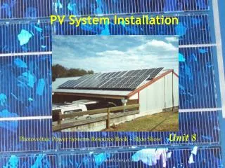
System Installation Examples. Hybrid Energy Systems – Slide Show Author: Geoff Stapleton, Global Sustainable Energy Solutions Editor: Paul Monsour, Brisbane and NorthPoint Institute of TAFE.

E N D
System Installation Examples Hybrid Energy Systems – Slide Show Author: Geoff Stapleton, Global Sustainable Energy Solutions Editor: Paul Monsour, Brisbane and NorthPoint Institute of TAFE (C) BIT Renewable Energy Centre
This slide presentation shows photos of hybrid power system installations undertaken over a number of years. Many of these systems had installation upgrades and are shown so you can appreciate that as an installer you may be faced with challenging situations. These pictures represent real life situations, not classroom hypotheticals. Note: Some of these installations would not meet the current Australian standards but in general were considered good practice at the time. Consider how you might do things differently now... Explanations are provided on each slide. (C) BIT Renewable Energy Centre
The systems in this presentation are hybrid power systemswhere a genset is a major source of energy, running daily in some cases. These systems in general supply larger daily loads, and have smaller batteries than the systems considered in the PV Power Systems module. While the design principles for these hybrids are different to smaller PV systems with several days of autonomy, the installation practices for the components are the same. This slide show has therefore been included for students of PV Power Systems, to provide additional examples of system installations. (C) BIT Renewable Energy Centre
System one2.1 kW PV - 48 Volt Interactive System • 28 * 75 Watt mono-crystalline solar modules • 24 * 2P1110 BP Solar PVStorFlooded Lead Acid Batteries(1110 Ah at 100 hr rate, 661 Ah at 10 hr rate) • Trace 48 Volt 3,300 VAsine wave inverter • PL60 Plasmatronic regulator • LPG generator 8.5 kVA (C) BIT Renewable Energy Centre
The architect had selected the water tank as the site for the solar array. This siting was not ideal because of afternoon shading from the western wall. (C) BIT Renewable Energy Centre
These trees will also cause shading in the morning! Make sure the customer is informed of any shading that will impact on the system performance! (C) BIT Renewable Energy Centre
The array consisted of 7 separate sub-arrays each with 4 modules wired in series.It was configured: 2 at the front, 3 in the middle, 2 at the back. There was insufficient space on the water tank to have the arrays mounted such that the bottom of the modules were just above the water tank. Shading would have occurred from the front arrays in the morning and afternoon, so they had to be staggered as shown (array on the left is raised more than middle, more than right). (C) BIT Renewable Energy Centre
The aluminum array frames are dynabolted to the tank. The cabling is run in conduit.The modules are wired 4 in series and then paralled to have only 2 wires going to junction box. (C) BIT Renewable Energy Centre
The cables from the array are connected in the junction box and two cables run down to the regulator. (C) BIT Renewable Energy Centre
The architect/builder dug out the area behind the water tank to install a shed to house the batteries,inverter, regulator and the LPG generator. The top of the shed has since been covered in dirt. (C) BIT Renewable Energy Centre
The installer supplied to the architect the minimum dimensions of the shed. The battery enclosure was to be 2.9 m wide. However, it was built 2.4m wide, hence the two batteries on the end! What does one do??? (C) BIT Renewable Energy Centre
Vent Battery Room and adjacent equipment room. Weatherproof doors have been installed on the front of the enclosure (not shown). There is a vent above the batteries and the doors have vents. (C) BIT Renewable Energy Centre
The equipment room. It is only about 1.6 metres high! It was 40 deg C on the day of installation. See next slides for explanation of equipment layout. (C) BIT Renewable Energy Centre
CB used for DC lights Interactive Inverter Regulator 24 V DC light . Two in series. One in generator room CB:Solar to Regulator AC Switchboard to house CB: Regulator to Switchfuse AC Power Point Battery Switchfuse Entry Point to Battery room isbelow top of batteries Equipment Room: Main Items (C) BIT Renewable Energy Centre
AC In: from Generator AC Out: To Switchboard DC Lights DC Lights Gen Control wires to Inv. AC from Inv Inv to Switchfuse Gen Control wires to house PV to Regulator Switchfuse to Batteries AC to House Regulator to Switch-fuse Equipment Room: Cable Layout (C) BIT Renewable Energy Centre
Note: Exhaust pipe now comes out here and goes up the wall to exit near roof LPG Generator in its own weatherproof enclosure (C) BIT Renewable Energy Centre
System two1.5 kW PV - 48 Volt Interactive System • 20 * 75 Watt mono-crystalline Solar Modules • 24 * 2P1110 flooded Batteries(1110 Ah at 100 hr rate, 661 Ah at 10 hr rate) • PSA 48 Volt 3,000 VA Interactive Inverter • PL40 Plasmatronic Regulator • Diesel Generator 4.5 kVA(supplied by customer) (C) BIT Renewable Energy Centre
PV modules mounted on the shed roof, currently being used as living quarters while the new house is being built. The array comprising; 5 parallel strings with 4 modules in series to form the string. (C) BIT Renewable Energy Centre
Batteries are located on southern side of shed. The shed is partitioned off to form a separate room. The original aim was to mount batteries in their own enclosure and the equipment in a cupboard. The owner built this separate room without consulting the installer, again the room dimensions did not allow the full number of cells to fit! (C) BIT Renewable Energy Centre
CB: PV to Regulator PV Regulator PSA 3,000 VA Interactive sine wave Inverter CB: Regulator to Switchfuse Regulator and Interactive Inverter (C) BIT Renewable Energy Centre
PSA Inverter 3,000 VA Interactive sine wave About 500mm between batteries and equipment Switchfuse positioned below tops of batteries Battery and equipment mounting (C) BIT Renewable Energy Centre
System Three1.2 kW PV - 24 Volt Interactive System • 16 * 75 Wattmono-crystalline Solar Modules • 12 * 2P1110 flooded Batteries(1110 Ah at 100 hr rate, 661 Ah at 10 hr rate) • PSA 24 Volt 3,000 VA Interactive sine wave Inverter • PL40 Plasmatronic Regulator • Diesel Generator 6.5 kVA (C) BIT Renewable Energy Centre
Generator Room Equipment Room The customer specified the PV modules to be in the same plane (C) BIT Renewable Energy Centre
DC Light Regulator and CB’s PSA Interactive Inverter Switchfuse CB for light Equipment layout (C) BIT Renewable Energy Centre
Room ventilation Circuit breakers mounted below top of batteries West wall North wall Hole in floor (not shown) It was originally planned that the inverter would be located in the left hand corner near the southern wall BUT the only access hole into the generator room was through the floor about 30cm from the middle of the western wall!! The generator was located against the western wall in the generator room . Mounted on the western wall was a fire fighting diesel pump, so it was not easy to go straight through the wall to the generator. Note! Battery cable should be mechanically protected over its entire length! (C) BIT Renewable Energy Centre
System Four600 W PV - 24 Volt Switched System • 8 * 75 Watt mono-crystalline solar modules • 12 * Battery Energy 2SG650(2 volt 650Ah gel battery) • Selectronics SE-32 24Volt 2,000 VA sine wave Inverter • Stanbury Scarf and Lord 50 Amp Battery Charger • PL40 Plasmatronic Regulator • Petrol Generator 4.4 kVA (C) BIT Renewable Energy Centre
Destination Site access? There was no access to this site by car. The installer had to use a wheel barrowto transport all equipment and walk about 700 metres on sand, narrow track and up the rise. (C) BIT Renewable Energy Centre
The hardest part of the journey was over the sand. Gel batteries were used in this installation as they are smaller and have no liquid electrolyte to spill. A fridge was also delivered to site by the same transport method! (As the site is a popular tourist spot the installer had to hire a third person to mind the vehicle while “the workers” traveled back and forth with equipment.) (C) BIT Renewable Energy Centre
These private cabins are located in a national park. The PV modules were originally raised to 50 degrees but NPWS said they were not visually acceptable and had to be lowered,hence the excess cable behind the modules. (C) BIT Renewable Energy Centre
Automatic Changeover Relay and contactor Switchboard to cabin Generator Cable. Generator located in box on eastern side of cabin Inverter Switchfuse Battery Charger Generator Only GPO Equipment Cupboard (C) BIT Renewable Energy Centre
Earth stake Battery Box Behind Equipment Cupboard (C) BIT Renewable Energy Centre
OverviewofDifferentSystem Installations (C) BIT Renewable Energy Centre
Generator Remote Switch Inverter CB: PV to REG Regulator CB: REGto Switchfuse Switchfuse (C) BIT Renewable Energy Centre
Regulator Manual Changeover Switch Dividing wall between batteries and equipment. Should be higher Inverter Switched Installation in Shed: Modules on Roof. There is now wire and mesh to minimise dust around the system. (C) BIT Renewable Energy Centre
Sine Wave Inverter Inlet for Petrol Generator Battery Charger (C) BIT Renewable Energy Centre
Regulator Controller Inverter Battery Charger Switched System in room in shed. Modules on Roof (C) BIT Renewable Energy Centre
Regulator Controller Battery Fuses Inverter Battery Charger Equipment Mounted in Cupboard: Batteries in Box (see next slide). Petrol generator mounted in corner of room. (C) BIT Renewable Energy Centre
Batteries mounted in box. Sloping lid to prevent tools etc from being placed on top of box. (C) BIT Renewable Energy Centre
Batteries Equipment Cupboard: See Next Slide Generator is housed in room on southern side of this brick shed The PV modules are mounted on the roof of the large shed. The brick shed houses the generator in one room, a cupboard for batteries and a cupboard for equipment. When the customer saw the size of the batteries, he did not build a full height cupboard but decided to have a shelf inside the generator room. Fortunately enough room was left above the batteries to use a hydrometer. The problem with this arrangement is that the system maintainer is exposed to the elements and has got wet on occasions! (C) BIT Renewable Energy Centre
Regulator Controller Inverter Charger Equipment Cupboard (C) BIT Renewable Energy Centre
Regulator Controller Generator Remote Switch Switchfuse Battery Box Inverter Charger System mounted on verandah with equipment in one cupboard and batteries mounted in a box. PV modules are mounted on the roof and the generator is mounted in a separate shed. (C) BIT Renewable Energy Centre
Battery Box System with modules on roof. Batteries in box on verandah and equipment is in the garage (see next slide) (C) BIT Renewable Energy Centre
Regulator Inverter in Box (C) BIT Renewable Energy Centre
OverviewofDifferentPackaged Systems (C) BIT Renewable Energy Centre
Small system containing a 200 watt Inverter and two 12V batteries contained within the box. (C) BIT Renewable Energy Centre
Pyramid Power Packaged System 8 75 W modules on tracker Within Pyramid is: -12 Batteries - Interactive Inverter - Regulator - Generator (C) BIT Renewable Energy Centre
AnotherPyramid (C) BIT Renewable Energy Centre
Container System:Within the container are two rooms;one for generator and one for batteries and equipment. (C) BIT Renewable Energy Centre
The End !! (C) BIT Renewable Energy Centre