Download

1 / 42
440 likes | 617 Views
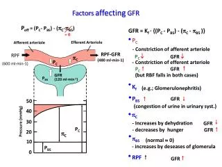
BASICS OF P OWER F ACTOR C ORRECTION. LOAD. Harmonics Reactive power Unsymmetrical load Flicker. GRID. Loads create disturbances. Different aspects of electrical power quality. Caused by:. Reactive power. Inductive loads, Power Electronics. Harmonics.

E N D
BASICS OF POWER FACTOR CORRECTION Basics of Power Factor Correction
LOAD Harmonics Reactive power Unsymmetrical load Flicker GRID Loads create disturbances Basics of Power Factor Correction
Different aspects of electrical power quality Caused by: Reactive power Inductive loads, Power Electronics Harmonics Power electronics, non-linear loads Commutation Converter and drives Voltage sags an swells Load variations, high inrush currents Unsymetric grids Unbalanced single phase loads Radio frequencies Ripple control Voltage interruptions Lightning, over load, switching operations Basics of Power Factor Correction
What are the different types of loads? Ohmic loads Inductive loads Lighting bulbs Electrical Motors Iron Transformers Resistive heating Reactors/chokes Overhead lines Under excited Capacative loads Synchronous Capacitors generators Underground cables Discharge lamps GRID Over excited Power electronic synchronous generators Basics of Power Factor Correction
j=0° I - Current U - Voltage Three different types of loads: 1. OHMIC-LOADS • In resistive circuits the voltage and current waveforms reach their peaks and troughs as well as the electrical zeros at the same instant of time. • The voltage and current are said to be in phase ( = 0°) and the entire input power is converted into active power. Thus, resistive circuits have a unity power factor. • The ohmic resistance does not depend on frequency. Ohmic loads U and I in phase Phase shift = 0 No penalty Basics of Power Factor Correction
U - Voltage j=90° I - Current Three different types of loads: 2. INDUCTIVE-LOADS • Most of the industrial loads are inductive in nature e.g. motors, transformers etc. Due to inductive reactance of the load, the current drawn by the load lags behind the voltage waveform electrically by an angle . • The magnitude of is proportional to the inductive reactance. Since the current lags behind the voltage, inductive loads are said to have a lagging power factor. • Impedance-XL = 2 * 3.14 * f * L Inductive loads U is 90° ahead of I 90° phase shift Penalty! Basics of Power Factor Correction
Three different types of loads: 2. INDUCTIVE-LOADS • Inductive loads cause a phase shift between current and voltage. • A positive as well as a negative power can be observed. Basics of Power Factor Correction
I - Current j=90° U - Voltage Three different types of loads: 3. CAPACITIVE-LOADS • Due to capacitive reactance of the load, the current drawn by the load is ahead the voltage by an angle . • The magnitude of is proportional to the capacitive reactance. • Impedance Capacative loads I is 90° ahead of U 90° phase shift Over compensation is risky! Basics of Power Factor Correction
QC S2 Q2 = Q1 - QC 2 Three different types of electrical power S1 Q1 1 P • S = Apparent Power • P = Active Power • Q = Reactive Power Basics of Power Factor Correction
Reactive Power ( kvar) = - 2 2 Q S P Q Q 2 C Q 1 S 2 Active Power Apparent Power = - j P S ² Q ² j 1 2 = + S S P ² Q ² ] [ KW 1 [ ] kVA j j cos = P/S = phase displacement angle j sin = Q/S S = uncompensated apparent power 1 j Q = S sin S = compensated power with 2 capacitors for compensation j Q = P tan Three different types of electrical power • S = Apparent Power • P = Active Power • Q = Reactive Power Basics of Power Factor Correction
What is Active Power? The amount of input power which is converted into output power, is termed as “active power” and is generally indicated by P. The active Power is defined by the following formula. [W] Ideally, entire input power i.e. apparent power should get converted into the useful output, i.e. heating of an oven, movement of an motor, light of an bulb. Basics of Power Factor Correction
What is Reactive Power? • Electrical machines work on the principle of conversion of electromagnetic energy.(e.g. electric motors, transformers). A part of input energy is consumed for creating and maintaining the magnetic field. This part of the input energy cannot be converted into active energy and is returned to the electrical network on removal of the magnetic field. This power is known as “reactive‘‘ power Q and is defined as follows. • [VAr] Basics of Power Factor Correction
What is Apparent Power? Applications of electrical equipment are based on conversion of electrical energy into some other form of energy. The electrical power drawn by an equipment from the source is termed as Apparent Power, and consists of active and reactive power. The current measured with a clamp amp indicates the apparent power. It is defined as follows: [VA] Basics of Power Factor Correction
What is the power factor? Power factor = cos cos-phi = P (kW) / S (kVA) Basics of Power Factor Correction
Typical power factors in industries Basics of Power Factor Correction
Why to improve the power factor? • System kVA- release • Reduction of power bill (short pay back time: 6-18 month usually) • Reduction of ohmic losses • Power Quality improvement (harmonics, voltage sags..) • Higher kW loading of transmission and distribution equipment and/or smaller dimensioning of this equipment (cable, transformer, bus bars,...) Basics of Power Factor Correction
How to improve the power factor? • PFC Capacitors • Over-excited synchronous generators • Active (real time) compensation • Reduce amount of inductive load • Usage of modern converter technology Basics of Power Factor Correction
Principle of PFC Basics of Power Factor Correction
65 0 95 Active Energy Reactive Energy Corriente Capacitor Current Current Principle of PFC Mechanical or thermal work Generation of magnetic field Supply Load Basics of Power Factor Correction
Methods of PFC • Individual compensation • Group compensation • Centralised automatic compensation • Combined compensation • Active (real time, by means of Semiconductors) PFC Basics of Power Factor Correction
Methods of PFC: 1. Individual (fixed) Compensation • Advantages • kvar produced on the spot • Reduction of line losses • Reduction of voltage drops • Saving of switch gear • Disadvantages • Many small capacitors are more expensive than one single capacitor of total equivalent rating • Low utilization factor of capacitors for equipment not often in operation In fixed compensation, capacitors are directly connected to the terminals of the individual load (e.g. motor, transformer), and switched by means of the load contactor or CB together with the load. Basics of Power Factor Correction
Methods of PFC: 1. Individual Compensation - lighting Basics of Power Factor Correction
Methods of PFC: 1. Individual Compensation - motor Basics of Power Factor Correction
Methods of PFC: 1. Individual Compensation - motor For compensating of asynchronous motors the capacitor output should be maximum 90 % of no load reactive power of the motor. Higher kvar ratings lead to self excitation of the motor after disconnection from the grid. Risk of over voltage > 1,1 * Unominal! Recommended kvar size ensures a PF of < 1 but > 0,9 in low load as well as full load operation of the motor. A thumb rule recommends: kvar = 35% of active power (kW) of a motor Active power can be found on the rating plate of a motor. Basics of Power Factor Correction
Methods of PFC: 1. Individual Compensation - transformer • PFC on LV bus bar • Compensation of no load reactive power of the transformer • Voltage increase on LV side Basics of Power Factor Correction
Methods of PFC: 1. Individual Compensation - transformers For compensation of no-load reactive power of transformers the kvar output of the capacitor is based on the reactive power consumption of the transformer itself. The recommended values compensate the magnetizing power of a not loaded transformer only. The following approximation formula can be used: Qo = So = io x SN / 100 Qo = Transformer no-load reactive power in kvar So = Transformer no-load apparent power in kVA io = Transformer no-load current in % of the nominal current SN = Transformer nominal power in kVA Basics of Power Factor Correction
Methods of PFC: 2. Group Compensation • Disadvantages • No load reduction, loss reduction, voltage drop reduction on individual load lines • Advantages • Reduction of capital investment • Losses reduced in distribution lines • Voltage drops reduced in distribution lines • Higher utilization factor of capacitors In group compensation, capacitors are connected to a group of loads (e.g. motors), and switched by means of the main load contactor or CB together with the load. Basics of Power Factor Correction
Methods of PFC: 3. Centralized Compensation • Advantages • Best utilization of the capacitors • Most cost effective solution • Easier supervision • Automatic control • Disadvantages • Load not lightened on distribution lines within a factory In factories with many loads of different output and operating times fixed compensation is usually to costly and non-effective. The most economic solution for complex applications is usually a centralized automatic capacitor bank, controlled by a automatic PF controller. Point of connection is usually in the main distribution panel close to the transformer. Basics of Power Factor Correction
Methods of PFC: 3. Centralized Compensation Basics of Power Factor Correction
Frequently asked questions • What is the thumb rule for selection of kvar size for motor fixed compensation? • How to find the active load of a motor for calculating the capacitor size? • In factories with many loads it is problematic to calculate the required capacitor output during planning status.1) Why?2) How to select a suitable kvar size? • When to select:A) Fixed B) Group C) Centralised - compensation Basics of Power Factor Correction
Methods of PFC: 4. Active Compensation • Advantages • Real time compensation • Reduction of reactive energy costs • Opens new fields of applications • Improvement of power quality • Disadvantages • Requires high capital investment • High engineering efforts required • Higher losses of electronic switches • Typical applications: • Cranes, Lifts • Spot welding, punching ... e.g. car industry • Paper mills, semiconductors, .... • All kind of short term loads Basics of Power Factor Correction
Methods of PFC: 4. Active Compensation Basics of Power Factor Correction
Methods of PFC: 4. Active PFC - Reference project • Caledonian Paper plc • Irvine, Scotland • Production of 325 tons deposited paper per year year • Total load: 47 MVA • 10MVA sensitive load • 11kV (50 Hz) factory grid supplied from 132 kV HV Scottish Power • Lowest voltage sag 34% of nominal voltages • 37 voltage sags per year Basics of Power Factor Correction
iN ua, b, c iL GRID Load EMC filter ist LCL-Filter IGBT-Converter C SIPCON DVR (LV) Methods of PFC: 5. Active harmonic filter Basics of Power Factor Correction
Example: Current reduction in main supply cable? HV Grid HV Grid Transformer 630 kVA, uk = 5 % Transformer 630 kVA, uk = 5 % Current = 666 A Current = ??? 300 kW cos = 0.65 300 kW cos = 0.65 M 3 ~ M 3 ~ Capacitor bank Qc = 10 * 25 kVAr Current reduction: ??? Basics of Power Factor Correction
Example: Required kvars for target PF of 0.98? HV Grid HV Grid Transformer 630 kVA, uk = 5 % Transformer 630 kVA, uk = 5 % Current = 666 A 300 kW cos = 0.65 300 kW cos = 0.65 M 3 ~ M 3 ~ Capacitor bankQc = ??? kvar Basics of Power Factor Correction
Example for PFC: Kvar calculation based on electricity bill (kvarh) • Question: • An electricity bill of a petrochemical factory shows a monthly demand of 720 000 kvarh reactive work • Monthly billing: 720 000 kvarh * x $ • Daily operation, 24 hours a day • What remedial measures have do be carried out to reduce the electricity bill? Basics of Power Factor Correction
Example for PFC: Kvar calculation based on electricity bill (kvarh) Answer: • Additional capacitor output has to be installed. • According the following formula the required kvar output can be calculated: Q in kvar = W in kvarh / time in h • Time = 30 days * 24 hours • Q = 720 000 / 30 / 24 = 1000 kvar • By installing a 1000 kvar (2*50+9*100) capacitor bank the customer will eliminate the kvarh consumption down to ZERO. Basics of Power Factor Correction
Example • Question: • A textile factory with a total load of 300 kW shows an actual power factor of 0.65 (phi=49,5°) • The local power utility asks for a target PF=0.95 (phi=18,2 °)What capacitor output is required to avoid surcharges for low PF? HV Grid Transformer 630 kVA, uk = 5 % 300 kW cos = 0.65 M 3 ~ Capacitor bank Qc = ?? kvar Basics of Power Factor Correction
Example • Solution: • Qc = P * (tang phi1 - tang phi 2) = 300*(tan (49.5) - tan(18,2)) = 252 kvar • For a proper fine tuning of the target PF we recommend a capacitor bank design: 25 + 25 + 50 + 50 + 50 + 50 kvar • Depending on types of loads, e.g. frequency converters, de-tuned capacitor banks should be used Basics of Power Factor Correction
Single line diagram essential for system study 110 kV Power uility 35 kV S "=310...360 MVA k 16 MVA 16 MVA 3x5 MVA Station 10 Station 15 n. o. 1.6 MVA 1.6 MVA 1.6 MVA 4 % 4 % 4 % 1x500 kW 320 kW 4x300 kW 5x300 kW 2x250 kW (Converter) (Converter) (Converter) (Converter) Harmonic Filter Basics of Power Factor Correction