Download
1 / 12
120 likes | 231 Views
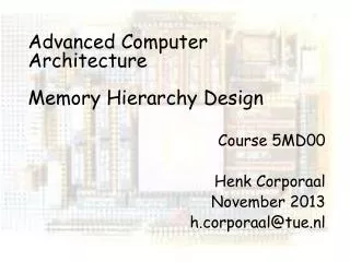
Lecture 4: Computer Memory. Memory basics: an RS Latch. The circuit below can remember! R and S are the inputs. In use, we never allow 1’s on both R and S (think of the inputs being controlled a switch).

E N D
Lecture 4: Computer Memory Computer Structures
Memory basics: an RS Latch • The circuit below can remember! R and S are the inputs. In use, we never allow 1’s on both R and S (think of the inputs being controlled a switch). • Remember that a NOR gate outputs a 1 only when both inputs are zero, otherwise output is 0. Looking at how the outputs feed back into the inputs, logically the outputs could be in state 1 shownbelow. = 0 R = 0 = 1 S = 0 Computer Structures
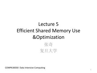
Changing latch states = 1 R = 0 = 0 • It is very important to remember that signals take time to get from input to output in logic gates. • Now imagine changing S to 1. The bottom gate will produce a 0 at Q a tiny bit later. So now the A gate will have 0 and 0 as inputs and the Q output will be 1. This is state 2 of the latch, with Q and Q now reversed • Imagine putting S back to zero again, R=0 & S=0 as in the beginning. The bottom gate still produce a zero a tiny bit later, because its inputs are now 0 and 1. The inputs to the top gate will then both be 0, so Q remains 1 and the latch stays in state 2, despite the fact that its inputs have gone back to where they were in state 1!! The latch has ignored the change in input – it has remembered and kept state 2 !! No matter what we do to S, the circuit stays in state 2 – the information is ‘locked’ in. • So can we ever get back to state 1? Yes but only by using the R (reset) input. If we put this to 1, then the top gate outputs a 0 a tiny bit later and so the bottom gate outputs a 1. We are back in state 1 and no changes to R will change this – state 1 is remembered and kept until we use the S input to go back to state 2. • This is how S-Ram basically works, but the flip flops need to be powered up, otherwise no memory! S = 1 = 1 R = 0 = 0 S = 0 = 0 R = 1 = 1 S = 0 Computer Structures
Inputs to a latch can come from different places, with different delays. In a computer, we need to be very certain about when changes to the latch can occur. On use of a computers clock is to make sure that memory changes are controlled A clocked RS latch is called a Flip-flop Only when C = 1 can R’ and S’ take the values of R and S. The circuit is therefore “a clock controlled storage element” When clock is High: “1” is stored for S = 1 & R = 0 “0” is stored for R = 1 & S = 0 When clock goes low, information is protected. Computer Structures
D-type Flip-flop An RS flip flop needs different inputs to set or reset the latch (and there is an illegal state if R and S are both 1). Simpler to use is the D flip flop, where the same pin can be used for set/reset (D = R, D = S). Notice that it is based on a clocked RS flip flop – ie nothing happens unless the circuit is enabled by a 1 on C. So to store a 1 (i.e.set Q as 1) we put a 1 on D. To store a 0, we put a 0 on D. Easy! Computer Structures
D flip - flop D Q C Q D type flip flop summary If the clock is 0, nothing can happen, and the current state, Qn stays the same as the previous one Qn-1 If the clock is 1, whatever is put on D gets stored as the new state Qn Note i) Q is always available as well Note ii) C acts as an ‘enable’ for the flip flop Computer Structures
Other memory circuits • The RS flip flop is the easiest active memory circuit to understand. • There are lots of possible flip flop circuits – JK flip flops, JK master slave flip flops, edge triggered flip flops, D type flip flops and more… • Manufactures are interested in how fast these circuits can store their 0’s and 1’s and how much powerthey consume in doing so. All this is rather advanced stuff, only for specialist computer hardware engineers. A good book for this stuff, at a reasonable level is • But remember that active circuits based on flip flop type circuits give us the fastest memory, for example that used in caches. Computer Structures
Bit line C Switch Word line Dynamic RAM (DRAM) 1 • Active SRam, though fast, is expensive. So most of the memory in your computer is some kind of DRAM. • DRAM is very simple – based on the charge stored on a capacitor. Capacitor charged up = 1, capacitor discharged =0. • The capacitor is actually that of the gate of an FET ~ 15 *10-15 farads (femto farads). • How does it work? • To write a value, 0 or 1 is put on bit line and word line ‘asserted’ to close the switch. C charges if a 1 (5 volts) on the bit line, or discharges for 0 (0 volts) • To read the value, bit line pre-charged (to 0) and word line asserted. Value in C appears on bit line (and sensed and amplified). This discharges C, destroying its contents, so another step: • The value sensed and amplified is put back on the bit line – refreshing C Computer Structures
Dynamic RAM (DRAM) 2 • DRAM has to be refreshed, if not read for a few ms. • Although access time can be 10ns, cycle time is much bigger (50-100ns) because of refresh and pre-charging. • Can be very big (to 1Gbyte) • Organised as two dimensional grids of memory cells (easier decoding, faster), with time multiplexed addresses (RAS and CAS needed) to reduce number of pins Computer Structures
Enable line R/W Line D7 Data bus D0 E R/W D Memory cells A single memory cell is not much more than a D flip flop – the Enable line is the flip flop clock, the D line combines the flip flops D input and Q output into one, and the R/W line determines whether D is doing a write (as an input) or a read (as an output). A byte memory cell will read or write 8 bits at once, as below, using the same Enable and R/W lines of course. Real memories use cells at least byte size (and up to 64 bits wide check this!!!) Computer Structures
16 address lines 65,536 pins/ one to enable each memory cell? Memory addressing (1) The CPU (and other devices) needs to be able to locate every memory cell. So each cell has an address (32 bits for a pentium). When the CPU wants to access a cell, it puts the cell’s address on the address bus. The address is used to assert the enable pin of the right memory cell, which then reads or writes the data from or to the data bus. Easy! But how to assert the right cell enable pin, if there are lots of addresses, e.g. for a 16 bit address (for 65,536 memeory cells), we would need an 8 to 65,536 decoder circuit: Computer Structures
A2 A1 S7 (111) A0 S6 (110) S5 down to S2 in here S1 (001) S0 (000) Memory addressing (2) How a decoder circuit can be built (3 to 8 example) Computer Structures