Download
1 / 45
460 likes | 755 Views
GPS and Future Directions in Positioning. Dennis D. McCarthy U. S. Naval Observatory. Briefing Overview. GPS System GPS Augmentations The Future. GPS. Critical component of the infrastructure Global utility providing positioning, navigation and timing (PNT)

E N D
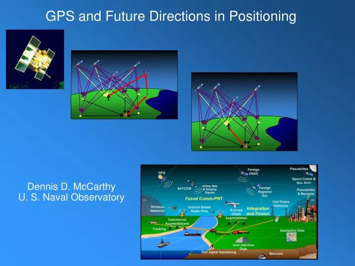
GPS and Future Directions in Positioning Dennis D. McCarthyU. S. Naval Observatory
Briefing Overview • GPS System • GPS Augmentations • The Future
GPS • Critical component of the infrastructure • Global utility providing positioning, navigation and timing (PNT) • Owned by the U.S. Government • Operated by the U.S. Air Force • Unlimited number of users • Free of direct user charges • Public domain • Performance improved by augmentations
Applications Satellite Operations Power Grid Management Trucking & Shipping Personal Navigation Communications Network Synchronization Surveying & Mapping Aviation Recreation Railroads Fishing & Boating Offshore Drilling
How It Works • Each satellite has a clock • Each satellite broadcasts where it is • Each satellite sends timing signal • Receiver has clock • Receiver determines distance to each satellite • Receiver determines position and clock correction
FAIRBANKS ENGLAND COLORADO SPRINGS SOUTH KOREA USNO WASH D.C. VANDENBERG, AFB CAPE CANAVERAL BAHRAIN Master Control Station HAWAII KWAJALEIN ASCENSION ECUADOR DIEGO GARCIA TAHITI SOUTH AFRICA ARGENTINA NEW ZEALAND GPS Segments Space Segment Satellite Constellation User Segment Ground Antennas MonitorStations Master Control Station Control Segment
GPS Space Segment • 6 orbital planes • Orbiting at approximate altitude of 20200 km every 12 hours. • L1 channel produces a Carrier signal at 1575.42 MHz with C/A and P Code • L2 channel produces a Carrier signal of 1227.6 MHz, but only P Code. • Codes are modulated on the carrier signal. • The C/A or Coarse/Acquisition Code (also known as the civilian code), is modulated and repeated every millisecond; • P-Code, or Precise Code, is repeated every seven days. • 14 Block IIA satellites • 12 Block IIR satellites • 5 Block IIR-M satellites • Transmitting new second civil signal (L2C) • Transmitting new military signal (M code)
C/A Code P Code L2 Carrier 1227.6 MHz L1 Carrier 1575.42 MHz GPS Signals
GPS Constellation StatusSatellite Age as of March 2008 16 14 12 10 Years 8 6 BLOCK IIA BLOCK IIR BLOCK IIR-M 4 2 Satellite 23 24 25 26 27 53 52 58 57 55 39 35 34 36 33 40 30 38 43 46 37 61 32 47 59 60 51 44 41 54 56 45
GPS Ground Control Segment • Generate navigation message Satellite • Position data • Clock data • Adjust as needed • Command & Control satellites • Perform maneuvers • Monitor satellite health The control segment keeps the GPS system operational and performing within specification
GPS User Segment • Unlimited • Broadcast system • More users can join system • U.S. & International • Multi purpose • Civil • Military • Commercial 18
PerformanceStandard Decreasing range error Continuous Performance Improvement • Accuracy • Assured Availability • Integrity • Resistance to RF Interference/Jamming
GPS Modernization • New GPS Operational Control Segment -- September 2007 • 5 new monitor stations integrated into network • 6 more in 2008 • Upgrading GPS ground segment – OCX – 2012 - 2016 • Will implement full functionality for L2C and L5 • Acquiring next generation of GPS satellites – GPS IIIA
Modernized GPS – Civil Signals • Second civil signal (“L2C”) • Designed to meet commercial needs • Higher accuracy through ionospheric correction • Higher effective power and improved data structure reduce interference, speed up signal acquisition, enable miniaturization of receivers, may enable indoor use • Began with GPS Block IIR-M in Sep 2005; 24 satellites: ~2014 • Third civil signal (“L5”) • Designed to meet demanding requirements for transportation safety (safety-of-life) • Uses highly protected Aeronautical Radio Navigation Service (ARNS) band • Begins with GPS Block IIF • First launch: ~2008 (GPS IIR-M Demo); ~2009 (GPS IIF); 24 satellites: ~2016 • Fourth civil signal (“L1C”) • Designed with international partners to enable GNSS interoperability • Begins with GPS Block III • First launch: ~2014; 24 satellites: ~2021
GPS Modernization Program Block IIA/IIR Block IIR-M Block III • IIR-M: IIA/IIR capabilities plus • 2nd civil signal (L2C) • M-Code (L1M and L2M) • Currently being launched • IIF: IIR-M capability plus • 3rd civil signal (L5) • Begin launch 2009 • Basic GPS • Standard Service • Single frequency (L1) • Coarse acquisition (C/A) code navigation • Precise Service • Y-Code (L1Y and L2Y) • Y-Code navigation • Backward compatibility • 4th civil signal (L1C) • Increased accuracy • Assured availability • Increased security • System survivability • Begin launch ~2014 Block IIF
Benefits of GPS Modernization • System-wide improvements in accuracy, availability, integrity, and reliability to meet US Space-Based PNT Policy • Higher standalone accuracy • More robust against interference • Provides separate, more secure military signal • Capability for second (L2C) and third (L5) civil signals • Delivers L1C for interoperability with other GNSS • Improved indoor, mobile, and urban use
Provide civil GPS and augmentations free of direct user fees on a continuous, worldwide basis Provide open, free access to information needed to develop equipment Improve performance of civil GPS and augmentations to meet or exceed that of international systems Encourage international development of PNT systems based on GPS Seek to ensure international systems are interoperable with civil GPS and augmentations Address mutual security concerns with international providers to prevent hostile use U.S. Policy Principles Outlined in 2004 Presidential Policy on Space-Based Positioning, Navigation, and Timing (PNT)
Defense Transportation State Interior NATIONALEXECUTIVE COMMITTEEFOR SPACE-BASED PNT Executive Steering Group Co-Chairs: Defense, Transportation ADVISORY BOARD Sponsor: NASA Agriculture Commerce NATIONAL COORDINATION OFFICE Host: Commerce Homeland Security Joint Chiefs of Staff NASA GPS International Working Group Chair: State Engineering Forum Co-Chairs: Defense, Transportation National Space-Based PNT Organization Structure WHITE HOUSE Ad HocWorking Groups
Key Executive Committee Actions • Five-Year National Space-Based PNT Plan • Summarizes EXCOM Departments’/Agencies’ planning for development, acquisition, sustainment, and modernization of U.S. space-based PNT systems • Interference Detection and Mitigation Plan • Department of Homeland Security coordinating USG capabilities to detect and mitigate sources of interference to GPS and its augmentations • National PNT Architecture • Provide national PNT framework/investment strategy to help guide future PNT system-of-systems investment– 2025 timeframe • International Cooperation and Consultation • Compatibility and Interoperability with other foreign systems
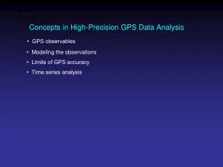
Problems • Orbits • Clocks • Atmosphere • Ionosphere • Multipath • Low number of visible satellites • High PDOP (position dilution of precision- a measure of the current satellite geometry) • Low signal to noise ratio • Low satellite elevation • Receiver
Augmentations / Alternatives • Space-based Augmentation Systems • WAAS – Wide Area Augmentation System • iGPS • Commercial Services: OmniSTAR, STARFIRE • Ground-based Augmentation Systems • LAAS - Local Area Augmentation System • NDGPS-National Differential GPS • USCG – U. S. Coast Guard • CORS-Continuously Operating Reference Stations • NOAA/NGS – National Geodetic Survey • JPL Real-Time Network • Carrier phase IGS • e-LORAN
Augmentation satellite provides correction signal Local monitor sites receive GPS signal and send data to central control site Space-Based Augmentations
WAAS • 38 Wide-area Reference Stations • 2 geostationary satellites • Two or three master stations • provide fast and slow GPS signal corrections • accuracy of better than three meters 95 percent of the time • Federal Aviation Administration (FAA) developing for use in precision flight approaches • accounts for GPS satellite orbit and clock drift plus signal delays caused by the atmosphere and ionosphere • Detects errors in GPS and notify users within 5.2 seconds (integrity) • Transparent - no post processing
iGPS • Proposed 66 low Earth orbiting Iridium satellite system • Earth stations • Operations center • Provides correction message for GPS signals • Requires new equipment but can use GPS antenna • Accuracy ???? • Constellation will need replenishment in 2014
Commercial Services • Omnistar, STARFIRE, Synchronetics • L-Band communication satellites • monitor sites • Processing and upload center • Requires special receiver equipment • Decimeter accuracy • No post-processing
Local monitor sites receive GPS signal and send data to central control site Ground-Based Augmentations
Local Area Augmentation System (LAAS) • Aircraft landing system based on real-time differential correction of GPS. • Local reference receivers at precisely surveyed locations send data to a central location at airport. • Signal is compared to the surveyed location and correction message transmitted to users via a VHF data link. • A receiver on the aircraft uses this information to correct GPS signal. • Designed exclusively for aircraft • Intended for use within 20 to 30 miles of installed airfield location. • No consumer-grade LAAS-capable GPS receivers • Accuracy better than 1 meter
Nationwide Differential GPS • Funded by DOT (Research and Innovative Technology Administration) • Maintained by Coast Guard • Needs special low-frequency receiving equipment • Accuracy • 0.5 meter near the reference station • Can degrade up to 1 meter/150 km • Typical accuracy is 1 to 3 meters • 2 to 5cm accuracy with Post Processing • High Accuracy NDGPS
Continuously Operating Reference Stations • National Continuously Operating Reference Stations (CORS) network • Online Positioning User Service (OPUS) • Atmospheric models • Troposphere • Ionosphere • Cooperative CORS provides access to GPS data disseminated by organizations other than the National Geodetic Survey (NGS). • Links to the web sites of cooperating organizations where users can download pertinent GPS data, positional coordinates, and related information.
JPL Real-Time Network • Global GPS Network • 20% of International GNSS Service • Internet data delivery • Accuracy • 10 cm horizontal • 25 cm vertical
Static High accuracy (about 5mm + 1ppm) Long distances. Data collected for several hours Rapid Static Form of static GPS Special ambiguity resolution techniques which use extra information Requires minutes instead of hours for observation Accuracy can reach the centimeter level on baselines less than 20km. Real Time Kinematic Uses a radio to link so that the reference station broadcasts the data obtained from the satellites to the rover instantaneously Limits baseline lengths accuracy will be in the range of 1-5cm. results are fast and co-ordinates are displayed in real time. C/A Code P Code L2 Carrier 1227.6 MHz L1 Carrier 1575.42 MHz Carrier Phase bit rate about 1 MHz
Strip Till 1 inch Accuracy 4 inch Row Crop Broadacre 1 foot $5,000 $15,000 $35,000 Real Time Kinetic • Components • Base Station • GPS receiver • RTK radio • Stable mounting structure • 12 volt power source • Rover • GPS receiver • RTK radio
e-LORAN • February 7, 2008 – DHS announced adoption of eLoran as a national backup to the GPS to mitigate any safety, security, or economic effects of a GPS outage or disruption • President’s Fiscal Year 2009 Budget Request: • Migrate administration of LORAN-C from USCG to DHS National Protection and Programs Directorate (NPPD), includes transfer of budget authority for funding and personnel • Prepare for conversion of Loran-C operations to eLoran • NPPD to oversee development of eLoran to provide national backup capabilities for positioning, navigation, and timing. • Coast Guard will continue operation of the system in 2009 on a reimbursable basis
Pseudolites Foreign GNSS GPS Space Comm & Nav Arch Aiding Data & Ranging Signals Foreign Regional Nav SATCOM Pseudolites & Beacons Fused Comm-PNT EMI EMI Cell Phone Networks Wireless Networks Ground Based Radio Freq Integration and Fusion Evolved GNSS Augmentation Commercial Augmentations Tracking Geospatial Data Networks User Interface Orgs PNT signal monitoring Beacons The Future
Fundamental Findings • National PNT Architecture’s main task is to generate PNT information and move it to the users • Current Architecture depends mostly on radio frequency-based operations • Multilateration (e.g., Global Positioning System, LORAN) • Beacons (e.g., Instrument Landing Systems) • Distributing augmentation data (e.g., National Differential GPS) • Most PNT challenges result from the inherent weaknesses of an RF-based architecture • Impedance and interference • Limits on accuracy and precision due to physics
Fundamental Findings • Many user needs are common across domains, but specialized needs still require specialized solutions • Application-centric and system-specific approaches have bred inefficiencies • Increasing demands will be placed upon the enterprise in the future • Expectations change faster than capabilities can keep up, so must design architecture for flexibility and adaptability • Current organizational constructs are not structured to ensure cooperation and information sharing • Many users accept reduced performance or increased risk over more burden, (size, weight, power, and cost) • Users are willing to accept marginally more burden when commensurate benefits are available
Fundamental Findings • “Dependent” PNT technologies offer significant capabilities • User bears “marginal cost” of accessing performance designed to meet the needs of the most demanding customers • “Autonomous” PNT technologies offer significant capabilities • User burden is based on required performance • Reliance on diverse PNT sources increases robustness and availability • Diversity within a phenomenology (e.g. GPS L1-L2C-L5 or Multi-GNSS) • Use of multiple phenomenologies (e.g. GPS-CSAC-INS or image-aided INS) • High levels of interoperability enable efficiency and source diversity • Interchangeability, (e.g. 2 GNSS + 1 LF + 1 Clock = 4D solution) • Communications capabilities offer potential for addition of PNT information • Timing synchronization, ranging, augmentation or integrity information
National PNT Architecture Strategy • Greater Common Denominator approach • Specialized needs still require specialized solutions • Divest US GNSS augmentations that are duplicative after capability is available from US GNSS modernization • Promote low-burden autonomous capabilities for special needs • Specialized capabilities are still needed in some applications and when cost per capability precludes a common solution
Use Multiple Phenomenologies to the Maximum Extent Practicable Rationale • Diverse PNT sources and data paths will be needed since no one method will meet any customer’s needs in all circumstances • Diverse PNT sources and data paths are inherently robust against single point failures • Encourage development and employment of equipment that integrates information from diverse sources and information paths • Should develop clear standards for use of foreign PNT systems for safety-of-life and critical infrastructure users • Establish standards for pseudolites and beacons to promote interchangeability and avoid interference • Pursue diverse space- and terrestrially-based PNT capabilities to support diversity in PNT sources and information paths
Interchangeable Solutions • Enhance efficiency and exploit source diversity • Use participation in international PNT-related activities to promote the interchangeability of PNT sources • Evolve standards, calibration techniques, and reference frames to support future accuracy and integrity needs • Identify and develop standards for PNT information exchange, assurance, and protection • Establish standards for the depiction of position information in local and regional operations • Combine information from GNSS, RF network, and precision clocks • Fuse data from GNSS, gyroscopes, and active/passive sensors • Use or discard PNT information from different sources as customers traverse impeded environments and environmental boundaries Rationale • Diverse sources must be synchronized, coordinated, and calibrated to allow user equipment to integrate their information more readily • The architecture must enable flexibility and adaptability to allow capabilities to keep up with improving expectations
Fusion of PNT with New and Evolving Communications Capabilities Rationale • RF imposes least user burden in communicating PNT information to mobile and remote users, but RF spectrum is limited • Potential for low-impact addition of PNT information to new and evolving communications systems for synergy with civilian emergency (911) service, and first responders • Study methods, standards, and potential capabilities for fusion of PNT and communications • Leverage/adapt RF broadcast and communication • Ranging information to known locations • PNT-related information (integrity, etc.) • May include SATCOM, cell phones, TV, AM/FM/satellite radio, etc.
Interagency Cooperation to Ensure Necessary Levels of Information Sharing • Establish a National PNT Coordination Function • Establish champions within the National PNT Coordination Function • Define, develop, sustain, and manage a PNT modeling and simulation core analytical framework Rationale • Current interagency organizational constructs do not ensure the necessary levels of cooperation and information sharing
Rationale Standards are fundamental to ensuring interchangeability Anticipated future measurement accuracy needs will be more demanding than they are today; reference infrastructures must be an order of magnitude better than required measurement accuracy Major improvements to reference frame definitions will be needed for the reference frame accuracies needed to support centimeter-level accuracy Standards and Reference Frames Evolve standards, calibration techniques, and reference frames to support future accuracy and integrity needs Proposed Transition Tasks • Determine accuracy of standards, calibration techniques, and reference frames needed to support projected real-time absolute positioning accuracy and integrity needs. Include: earth-fixed and celestial reference frames, earth orientation, grids, timing, frequency, physical models, and data transfer
Web-based Information • PNT.gov established to distribute information on the U.S. National Executive Committee • Information on U.S. policy, Executive Committee membership, Advisory Board and frequently asked questions • All recent public presentation • GPS.gov established for public information about GPS applications