1 / 4

实验一 可编程定时器/计数器(8253)

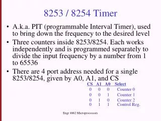
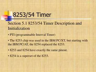
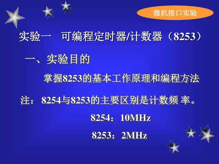
微机接口实验. 实验一 可编程定时器/计数器(8253). 一、实验目的. 掌握8253的基本工作原理和编程方法. 注:. 8254与8253的主要区别是计数频 率。 8254:10 MHz 8253: 2 MHz. 定时器/计数器. 二、实验内容. 1、 将计数器0设置为方式0,计数器初值为 N(N≤0FH), 用手动逐个输入单脉冲,编程使计数值在屏幕上显示,并同时用逻辑笔观察 OUT0 电平变化(当输入 N+1 个脉冲后 OUT0 变高电平)。

Download Presentation

实验一 可编程定时器/计数器(8253)

An Image/Link below is provided (as is) to download presentation Download Policy: Content on the Website is provided to you AS IS for your information and personal use and may not be sold / licensed / shared on other websites without getting consent from its author. Content is provided to you AS IS for your information and personal use only. Download presentation by click this link. While downloading, if for some reason you are not able to download a presentation, the publisher may have deleted the file from their server. During download, if you can't get a presentation, the file might be deleted by the publisher.

E N D

Presentation Transcript


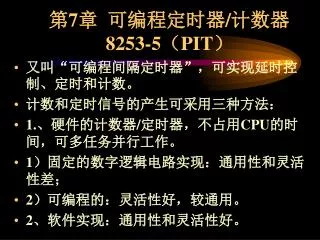
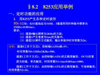
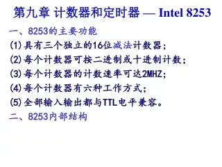
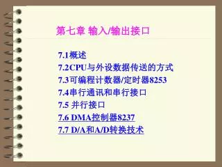
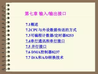
  1. 微机接口实验 实验一 可编程定时器/计数器(8253) 一、实验目的 掌握8253的基本工作原理和编程方法 注: 8254与8253的主要区别是计数频 率。 8254:10MHz 8253:2MHz

  2. 定时器/计数器 二、实验内容 1、 将计数器0设置为方式0,计数器初值为N(N≤0FH),用手动逐个输入单脉冲,编程使计数值在屏幕上显示,并同时用逻辑笔观察OUT0电平变化(当输入N+1个脉冲后OUT0变高电平)。 2、将计数器0、计数器1分别设置为方式3,计数初值设为1000,用逻辑笔观察OUT1输出电平的变化(频率1HZ)。
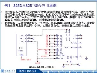
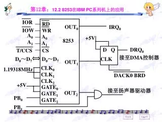
  3. 定时器/计数器 三、实验电路(1)

  4. 定时器/计数器 实验电路(2) 8253 控制寄存器地址 283H 0C403H 计数器0地址 280H 0C400H 计数器1地址 281H 0C401H

More Related