Download
1 / 37
400 likes | 545 Views
National Fusion Research Center, KOREA. The 6 th IAEA Technical Meeting Control, data Acquisition, and Remote Participation or Fusion Research 4 – 8, June, 2007, Inuyama, Japan. Implementation and Initial Commissioning. of KSTAR Integrated Control System. June. 5. 2007

E N D
National Fusion Research Center, KOREA The 6th IAEA Technical Meeting Control, data Acquisition, and Remote Participation or Fusion Research 4 – 8, June, 2007, Inuyama, Japan Implementation and Initial Commissioning of KSTAR Integrated Control System June. 5. 2007 Presented by Mikyung Park on behalf of KSTAR Control Team
KSTAR Integrated Control System Introduction Local System I&Cs Summary Start of Commissioning Contents 1 2 3 4 5
1 INTRODUCTION
Current Progress of KSTAR • Current Progress • 1. Completion of vacuum commissioning of • Current Lead System • 2. VV & CR vacuum commissioning in progress • 3. He Refrigerator System under installation • 4. Performance test of MPS in progress • 5. ECH System under commissioning • 6. Completion of Main Control Room • Afterward schedule • Completion of Assembly : 8. 2007 • Cool-down Start : 2. 2008 • Charge-up Start : 4. 2008 • 1st Plasma : 6. 2008
28MW 16MW 6MW Milestone of KSTAR Phase II Phase III Phase IV Phase I Initial Operation Steady-state Op. Research High beta AT Operation Steady-state AT • First Plasma • SC Tokamak Operation Technology (3.5 T) • D-shaped Plasma (1 MA) • H-mode Operation • Long Pulse Operation (over 100 s) • AT Operation Technology (< 20 MW) • ITER Pilot Device • Long Pulse Operation (over 300 s) • AT Operation Stabilization (> 20 MW) • ITER Satellite • High beta AT mode & long pulse • Material Test for DEMO Objective 300 s 100 s 20 s 0.5 s 300 s 3.5 T 1.5 T 3.5 T 0.5 MA 1 MA 2 MA LHCD ECH ICRH NBI-I
2 KSTAR Integrated Control System
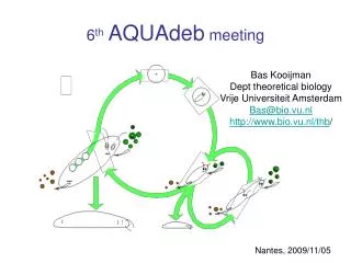
KSTAR Integrated Control System • Integrated the heterogeneous local systems such as VME, cPCI, PXI, PLC, cFP with EPICS • Basically, Linux-based system except some diagnostic systems • Five Different Networks - Machine network, dedicated Timing network, Experimental data network, Real-time network, and dedicated Interlock network • Two Databases - EPICS ChannelArchiver : operation data management - MDSplus : experimental pulse data management - MySQL : signal information data management • Development software - EPICS r3.14.8.2, MDSplus v.1.8.2-Jan.02.2007, MySQL, Qt R4.2.1, Linux Kernel 2.6.9, Vxworks Tornado2.2, etc
_ Configuration Supervisory Control System Fire Wall Operation Control Data Management OPI & Visualization Central Controller Time & Synchronization Display Wall Storage Area Network (SAN) Data Analysis Server Operator Interface OPIs Radiation Monitoring Discharge Control Personal Safety Storage System Control Network (Ethernet) Plasma Control System Interlock System Channel Archiver MDSPlus Server CA Gateway Machine Network (Ethernet) Experimental Data Network (Ethernet) Real-Time Network (Optical/RFM) Interlock Network (Optical) Timing Network (Optical) Vacuum Monitoring& Control System Tokamak Monitoring System Helium Refrigeration System Current Lead System Quench Detection System Magnetic Power Supply Fueling & GDC Heating System (ECH/ICRH) Diagnostic System
Central Controller Interfaces Channel Access (Ethernet) for machine control Reflective Memory Network - MPS control - Monitoring PCS/MPS in feedback operation Timing network Hardwired interlock signals - Send/Receive interlock status Features Integrated Control for Plant Operation - Operation mode control Operation/Discharge Sequence Control Monitoring Plasma control system & Magnet Power Supply - watchdog for feedback operation Sharing H/W with Timing System Multipurpose I/O PowerPC CPU Reflective Memory Central Timing Unit Machine NetworkEhternet CA Protocol Hardwired Interlock Signalto Interlock system Optical Timing Network RT-NetworkReflective Memory based Low latency / dedicated Network Example of operation sequence
Time & Synchronization System • New Timing Board developed • Platform changed from VME to PMC • Assembled in Controller board together, • Platform-independent • Central timing & Local timing functions • implemented in single board • GPS time & clock used as reference • Dedicated Timing Network with 1Gbps • transfer rate Timing Board (CTU/LTU) E-08, OLZETEK, Inc exhibits the timing board.
Data Archiving System Operator interface & Visualization System Control Network Data Analysis Server Storage Area Network (SAN) Storage Area Network (SAN) Channel Archiver Server MDSPlus Server Centralized Storage System • Pulse operation relateddata such as diagnostics, PCS, etc, Experimental Data Network Machine Network • 24 hours operation data • plant monitoring data Local Control Systems Pulse operation related Systems
Machine Interlock System • Composed of 1 supervisory interlock system and 11 subsystems • Implemented with PLC, in redundant system • Using dedicated interlock network, ControlNet • About 120 events handling for 1st operation • About 80 commands and status • We have finished installation & communication test • In present, we are revising signal I/Os and performing FMEA • In end of this year, we will expand system for ICRH, Baking system, etc. • We also have Personal safety system and Radiation monitoring system.
Main Control Room • In Equipment room Central controller & Timing Plasma control system Interlock & Safety systems Radiation monitoring system OPI servers Network main distribution frames • Features 22 operator’s seats Linux-based OPI servers - Only monitors in operator's seats - advantages in temperature and noise • 12 x 70” DLP cube system • 15 CCTV camera operated
3 Local System I&Cs
Tokamak Monitoring System • To monitor the cryogenic and structural behavior of KSTAR device • Total about 1,000 sensors have been installed - Temperature sensor : Cernox - Strain gauge : active-dummy - Displacement sensor - Hall sensor - Acoustic Emission sensor • All the sensors were tested in the room temperature • PXI-based DAQ system was selected. - one system for temperature and hall sensors - the other system for strain and displacement sensors • All the measurement data and monitoring status are integrated with EPICS
_ Sensor Installation Temperature sensors (Cernox) Cryogenic strain sensor (active-dummy) Displacement & AE sensor
Main Control Room Giga-bit Machine Net PXI system (EPICS IOC) Signal Conditioning cFPoint OPI#01 OPI#02 PT-100 sensor (Temp., Hall sensor) (Strain, Displacement) SAN Storage GA Gateway CA Archiver (TMS 1378PVs / sec) _ DAQ System and Data Archiving Data Acquisition Speed : 10 Hz Data Archiving Stored in Operation DB(CA Archiver) No. of CH : 1378 Repetitive archiving : 1Hz Archiving when exceedthe threshold value TMS IOC 1 >1113PVs TMS IOC 2 >265PVs P1-28, “Software Development of the KSTAR Tokamak Monitoring System,” presented by K.H.Kim
Vacuum Monitoring System • Vacuum Pumping System • VV pumping system, CR pumping system, • roughing & backing system • VV Pumping start : 19th, May • CR Puming start : 4th, June • Local Control System • cFP, LAN-Serial Converter, EPICS soft-IOC • Independent Local I&Cs for VV and CR, • We have finished the development and are • carrying out the commissioning
_ Configuration of Local I&C Interlock Sequence Operation PLC Tag Remote Operation Data Archiving EPICS Soft-IOC Machine network/Ethernet Async server (LAN-serial) Compact Fieldpoint RS232(485) Hard-wired Turbo-pump Controller Cryo-pump Controller Vacuum gauge monitoring Pumps monitoring cFP - Embedded CPU Valve, Pump control Valve, Pump status Cryostat Control rack
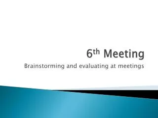
Current Lead System • He Control System, Current Lead Box, Current Lead, and Pumping System • Local Control System • PLC, Serial Converter, EPICS soft-IOC • Finished the CLB vacuum control system • and carrying out the commissioning • We are implemented of interface with the • He control system KSTAR Tokamak Superconducting Bus-line Current Lead System CL (Current Lead) Pumping System Cryogenic System He Control System He Transfer Line Current Lead Box • Mechanical Pump • Diffusion Pump • Super Trap • Control unit • Liquid Helium (LHe, 4.4 K, 1.3 bar) • Supercritical Helium (SHe, 4.5 K, 5 bar) • TS Helium (50 K, 20 bar) Normal Bus-bar MPS (Magnet Power Supply) (20 – 40 kA)
S S D D 1 1 E E R R 0 0 0 0 I I W W 8 8 - - X X 0 0 R R 0 0 6 6 1 1 E E 9 9 D D D D - - 2 2 R R R R 2 2 O O O O 6 6 A A L L A A R R M M C C A A L L L L W W A A T I I T N I I N G G d d i i g g i i t t a a l l A A L L L L C C A A L L L L 2 2 - - W W R R I I E E H H E E A A D D S S E E T T _ Configuration of Local I&C Remote Operation Data Archiving Interlock Sequence Operation PLC Tag Touch Screen (Local OPI) EPICS Soft-IOC Machine network/Ethernet AB PLC Ether-ip AB PLC Ether-ip ETOS-200 Serial Converter Valve control He control Mass flow monitoring Temp. monitoring RS232(485) Hard-wired Cryo-pump Controller Chiller, etc CR Valve Control He Level Pres. Transmitter Voltage Tab Q-PLC Vacuum Gauge Controller MFC Valve control Pump control Interlock Sequence Operation GPIB Vacuum gauge monitoring Pumps monitoring Chiller, etc. monitoring Cernox Sensors Pt. Sensors
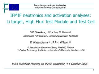
Magnet Power Supply System • Local control system • 1TF, 7 PF systems • VME/vxWorks/EPICS • Integration with Central Control System • Channel Access: Status monitoring & • Operation commands • Reflective Memory: fast feedback data • from Plasma Control System • TFmagnet power supply • 40 kA, 25 V unipolar • IGBT • PF magnet power supply • 25 kA, 1100 V, bipolar • Thyrister, 12 pulse • Blip resister insertion system TF MPS Inverter stack
Control system CPS APS Gyrotron IGBT switch tank HPS Dummy Load ECH System • Local control system • PLC (POSFA) System • - High voltage power supply control • - Waveguide switch control • - Utility monitoring (water, air pressure, He) • Local interlock • Completion of Integration with Central Control Systemand commissioning • EPICS SoftIOC • - PLC communication driver / Ethernet • - Waveform measurement (RF power) • Electron Cyclotron Heating System • 84GHz, 500kW Gyrotron • Complete the installation • the Gyrotron test in progress
Helium Refrigerator System • Helium Refrigerator • Cryogenic helium supply to SC magnets • 9 kW @4.5 K • Manufacturer : Air Liquide (France) • Local Control System • H/W : Siemens PLC with ethernet comm. Processor (CP443-1) • S/W:SIMATIC PCS7 • Interface H/W:Ethernet interface card • Interface S/W:EPICS IOC with S7PLC driver* • Communication method:Siemens S7PLC Communication*(by Dirk Zimoch in PAUL SCHERRER INSTITUT) Cold Box Tokamak Interface Compressor
Quench Detection System • Installation of 83 quench voltage detectors for KSTAR was finished and the user-interface is developed • KSTAR quench detection system was tested at the room temperature. • Before the KSTAR operation, various tests for guaranteeing the stable operation of this system @ CS Model Coil will be carried out • Design Criterion • HV Isolation up to 15 kVdc, 10 kVac : Same as superconducting magnet • Check system for voltage wire breakage and short circuit before & after operation • Noise filter • Common mode & Normal mode surge voltage protection • Low Normal Quench Voltage Criterion 100mV~300mV • Non-Electrical Detection form Mass flow meter & Temperature sensors
_ Quench Protector & Detector Voltage taps PF power supply & quench protection • Quench Protection circuit • DC circuit breaker • Thyristor commutation circuit • Dump resistor • Decay time constant : 7 sec. @TF • 4 sec. @PF • Protection delay • Requirement : < 150 msec • Real measure : < 80 msec
TF MPS Fast Discharge OR Logic OR Logic _ Schematics TF Quench Signal Integrator F/O Machine Network Quench Quench detector Set/Read Interface TF system PF MPS Fast Discharge Quench Quench detector PF Quench Signal Integrator Operator Interface F/O Quench Quench detector Interface PF system Quench Quench detector
4 Start of Commissioning
Vacuum Pumping System Vacuum Vessel Evacuation Vacuum pumping system Total Volume: 100m3 Surface Area: 587m2 Welding Length: 1.6km # of sealing: 100 4 5 Cryostat Evacuation Total Volume: 460m3 Surface Area: 2,904m2 Welding Length: 1.7km # of sealing: 207 3 Pumping System Evacuation : 2007. 4 Current lead system TF Bus & Current Lead Evacuation : 2007. 1. 1 PF Bus & Current Lead Evacuation : 2007. 3. 2
Residual Gas Analyzer H2O N2 Vacuum Vessel Commissioning • VV Pumping start : 19tht, May • Target of VV pressure : 5.0E-07 mbar • 1.35E-07 achieved • CR Pumping start : 4th, June Vacuum Vessel Pressure • CR Vacuum pressure @ 4th, June 1.35E-07mbar
CLB Vacuum Commissioning • TF Current Lead and Busline : 15th, Jan. • Target of pressure : 1E-04 mbar • 1.8E-06 achieved • PF Current Lead and Busline : 19th, March • Target of pressure : 1E-04 mbar • 6.7E-05 achieved Full-range gauge at PF CLB : 6.08E-05mbar Full-range gauge at TF CLB : 1.89E-05mbar
5 SUMMARY
SUMMARY • The KSTAR, which is under constructed aiming at the completion on August, 2007, is on the final assembly phase. • Also, the KSTAR control system has been developed to integrate many local systems with heterogeneous platforms using EPICS, the first attempt in Fusion device. • The KSTAR control system has been developed with expendability for the future long-pulse operation. • We have finished successfully the commissioning of TMS, VMS, ECH, and the other systems are planned to commission by August, 2007.
Thank you for your attention !