Download
1 / 16
160 likes | 273 Views
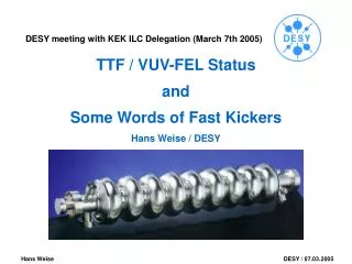
Layout of the Synchronisation System for the VUV-FEL. Dipl. Ing. Henning Christof Weddig DESY Hamburg. RF System Requirements. System Length 200 m (VUV_FEL); 3 km (XFEL) RF Phase Noise (within macropulse – 1 ms) 0.05 o RMS (at 1.3 GHz) ~0.1 ps RF Phase Noise (during 100 ms time)

E N D
Layout of the Synchronisation System for the VUV-FEL Dipl. Ing. Henning Christof Weddig DESY Hamburg DESY MHF-p
RF System Requirements System Length 200 m (VUV_FEL); 3 km (XFEL) RF Phase Noise (within macropulse – 1 ms) 0.05o RMS (at 1.3 GHz) ~0.1 ps RF Phase Noise (during 100 ms time) 0.15o RMS (at 1.3 GHz) ~0.3 ps RF Phase Stability (short term <1 minute) <0.5o (at 1.3 GHz) ~1 ps RF Phase Stability (long term) <5o (at 1.3 GHz) ~10 ps RF frequency range 1 MHz – 2.8 GHz DESY MHF-p
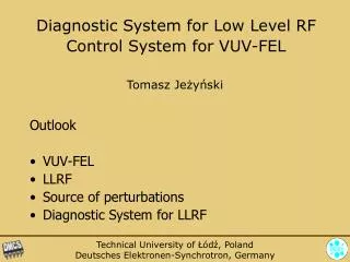
System components • Ultra high stable master oscillator • RF distribution system (length at VUV-FEL about. 200 m) • Temperature stabilized coaxial cables • Local 1.3 GHz/2.856 GHz frequency generation • Fiber optic and coaxial system to monitor and correct long term phase drifts DESY MHF-p
Frequencies to be distributed • the exact frequencies are multiples or divisions of the 9.027775 MHz reference frequency • 1 MHz (timing of complete machine) • 9 MHz (master reference frequency) • 13.5 MHz (Laser “new”) • 27 MHz (Laser “old”) • 54 MHz (Laser for future use) • 81 MHz (distribution frequency) • 108 MHz (Streak camera [near RF Gun; Experimental Hall]) • 1300 MHz (reference frequency for the linear collider) • 1517 MHz (reference frequency for beam position monitors) • 2856 MHz (“LOLA” = transverse deflecting cavity for bunch measurements) DESY MHF-p
Block diagramme of MO (low level part) DESY MHF-p
Phase noise requirements for the 1.3 GHz reference frequency DESY MHF-p
Phase noise performance of a 27 MHz crystal oscillator DESY MHF-p
Phase noise performance of a 81 MHz crystal oscillator Phase noise is better above 400 Hz from carrier! DESY MHF-p
MO front panel(low level part) DESY MHF-p
Layout of the Reference frequency distribution system for TTF2 DESY MHF-p
The problem of long coaxial distribution links:Attenuation of coaxial cable vs frequency DESY MHF-p
Phase stability of coaxial cable vs. Temperature½ ´´ cable DESY MHF-p
Phase stability of coaxial cable vs. Temperature7/8 ´´ cable DESY MHF-p
Advantages and disadvantages of coaxial cables Coaxial cables for distribution: - high attenuation (e.g. 7/8“ @ 1.3GHz A / 100m = 8dB) - physical dimensions - require temperature stabilization - can cause ground loops and pick up EMI Fiber Optics for monitoring : - require active temperature stabilization - the system components are more expensive in comparison to coaxial line system components - high amplitude noise of a FO link Solution: A combination of both technologies will be implemented and studied at TTF2. DESY MHF-p
Fiber optic distribution scheme DESY MHF-p
First results of fiber optic stabilization DESY MHF-p