Download
1 / 19
190 likes | 312 Views
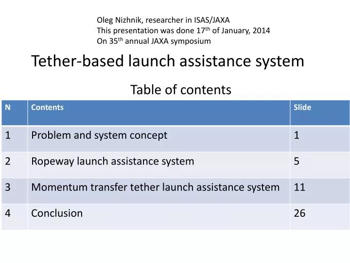
Oleg Nizhnik, researcher in ISAS/JAXA This presentation was done 17 th of January, 2014 On 35 th annual JAXA symposium. Tether-based launch assistance system. Table of contents. Problem: cannot improve rocket engines Because rocket engines Isp is nearing physical limit. LOX/CH2 limit.

E N D
Oleg Nizhnik, researcher in ISAS/JAXA This presentation was done 17th of January, 2014 On 35th annual JAXA symposium Tether-based launch assistance system Table of contents
Problem: cannot improve rocket engines Because rocket engines Isp is nearing physical limit LOX/CH2 limit LOX/LH2 limit
Problem: After 20 years of chemical rockets “improvement” performance of launch vehicles does not improve Rockets are evolving to carry larger payloads Payload Other parameters do not improve steadily Yearly launch capacity Payload mass fraction Launch cost Columbia disaster
Concept of launch assistance Concept of using tether for launch assistance: Instead of internal fuel energy, external source of electric energy used Part 3 Part 2 Solar battery Orbital anchor Final orbit Aerostat anchor Momentum Transfer tether Momentum transfer Rocket acceleration Ropeway scceleration Ground power network Start もとの発表リスト: [1] O. Nizhnik, “A Low-Cost Launch Assistance System for Orbital Launch Vehicles”, International Journal of Aerospace Engineering, Volume 2012, Article ID 830536, doi:10.1155/2012/830536, June 2012, pp. 1-10 [2] Nizhnik, O. “The Space Mission Design Example Using LEO Bolos”, MDPI Aerospace 2014, vol. 1, No. 1, pp. 31-51 ,doi:10.3390/aerospace1010031
2. Ropeway launch assistance Ropeway launch assistance system simplified diagram
There are merits of using balloon instead of heavier-than-air aircraft x Disadvantages of heavier-than-air aircraft Full explanation can be found in [1], briefly: Replacing rocket engine with jet engine do not reduce cost because of jet engine high power density 2) Aircraft is piloted 3) Total payload improvement limited to 15% 4) Ascent is too slow to use cryogenic fuel in rocket Pegasus-XL ロケット 「退社」 Advantages of balloon o • Cheap[10W/USD]and long-life ground-based electric motors are used • Flown weight reduction 50 times [Pegasus/Stargazer weight 200 tons」 • Cannot be directly replaced with solid-fuel booster • Ascent time to rocket start altitude is 3-7 minutes, allowing cryogenic fuel in rocket Sample of ropeway-assisted launch performance 6000hp electric motors bring 951kg rocket to 24km altitude in 3 minutes. Necessary balloon lifting power is 5.5 tons(0.8 mln. m3 NASAballoon is ok). Rocket bring 21.4kg payload to 185km low-earth orbit. Haas ロケット 「退社」
Rocket launch simulation • 2-stage rocket designed automatically using Scilab script. • Simulated components are payload, tanks and engines. Tank weight estimated using polynomial fitting from [3]. Engine type is Ottobrunn-300N. Number of engines selected automatically. • Other components (valves, structural, pipes, sensors, controllers) are not simulated • Rocket design is verified with simulated lift-off and engine burn. Result of orbital simulation Space 2nd stage burn 1st stage burnout Stable orbit Y distance (m) Atmosphere Separation from ropeway Surface To center of Earth X distance (m) [3] J. R. Wertz, D. F. Everett, J. J. Puschell, “Space Mission Engineering: The New SMAD”, Published by Microcosm Press, Hawthorne, CA, USA, 2011. ISBN 978-1-881-883-15-9
Aerostat altitude versus maximal rocket wet mass High wind pressure Negligible wind pressure With the current rope materials, rope above 45km will break under its own weight. Therefore, maximal rocket wet mass is reduced as aerostat altitude increases. Approximately,7mm2 cross-section Dyneema SK90rope can carry m<1990-0.04337*h, m-rocket mass(kg) , h-aerostat altitude (m)
Payload to orbit vs aerostat altitude High wind pressure Negligible wind pressure On high altitude, rocket weight is reduced, reducing payload accordingly With 2-ton wet mass and non-aerodynamic shape (form factor=0.6) rocket cannot reach the orbit from sea level Approximately, with 24km aerostat altitude, launch assistance delivers 2.2 km/s delta-v. This improvement come from 1.5km/s air resistance reduction, 0.6 km/s due initial altitude and 0.1 km/s due initial speed at separation point.
The launch cost dependence on balloon altitude Effect of air resistance Effect of overstressed rope Optimal launch weight 風圧力は高い高度 風圧力はほとんどない高度 More detailed economic calculation can be found in [1]
3. Momentum-exchange tether launch assistance • Payload connected to • Momentum-exchange tether 2. Payload rotate half-period with tether 3. Payload separate from tether and goes to orbit • System features: • Large acceleration, can boost sub-orbital payloads • Tether must be on LEO altitude, above 240km • After launch assistance, tether orbit must be re-boosted by ion motors or magnetic drive • Tether must be long (several km)
The orbital diagram of momentum-transfer launch assistance system 1-final payload orbit after release 2-tether orbit before capture 3-tether and payload orbit after capture 4-tether orbit after release 5-suborbital payload path before capture
In the rarefied air with density gradient the torque act upon tether, causing it to rotate in prograde direction. Airspeed=(Orbital Speed ) + ( Tip Speed) Less dense air Orbital speed vector Airspeed=(Orbital Speed ) More dense air Airspeed=(Orbital Speed ) - ( Tip Speed)
Steady-state air-induced tether tip speed Longer tethers has higher steady-state speedTherefore, tethers longer than 30 km will break before reaching steady-state speed (if existing materials only considered)
Spin-up time [to 63% of steady-state speed] In the altitudes range 550-700 km it is possible to select tetherlength to cancel out effects of solar weather on atmosphere scale. For other altitudes, 2-3 times variations of steady-state speed with phase of solar cycle are expected. Besides this line rotation speed will vary depending on phase of 11-year solar cycle
Initial tip speed to overcometidal stabilization At initial tip speed, movement of tether switch from libration to rotation
Effect of counterweight on momentum of inertia of tether and spin-up energy Counterweight increase momentum of inertia of tether, making spin-up of tether and payload capture more difficult. Only improvement is marginal reduction in micrometeoroid protection weight.
Sensitivity study of payload mass to technological improvements Design using current-age technilogy:11.5 tons orbiting tether boost 250kg payload、giving it 0.76 km/s delta-v. With Isp=360s rocket that delta-v translates to 43kg payload increase (+21%) System bottleneck:Tether/Payload increase is only1/400
Conclusion Solar battery Orbital anchor Final orbit Aerostat anchor Momentum Transfer tether Momentum transfer Rocket acceleration Ropeway acceleration Ground power network Start • To enable tether-assisted space launch, 3 main developments are obligatory: • Launch frequency of small (<50kg) payloads above 50 launches/year • 2-ton wet mass launch vehicle with appropriately lightweight valves, piping and sensors. • Increase of power density of orbiting spacecrafts to 10 W/kg. (in 2011, it was 2W/kg)