Download
1 / 14
140 likes | 146 Views
This presentation discusses the different maintenance schemes and blanket concepts for the ARIES-CS power core, including field-period based replacement and port-based replacement. It also explores the use of different blanket classes and structural materials. The down-selection process for Phase II is outlined, as well as the advantages and considerations for each maintenance scheme.

E N D
ARIES-CS Power Core Options: Decision Factors and Selection for Phase II A. René Raffray University of California, San Diego ARIES Meeting Madison, WI September 16, 2004
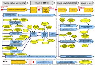
Outline • Phase I Engineering Effort - Maintenance approaches - Blanket designs • Down Selection for Phase II
Engineering Activities During Phase I of ARIES-CS Study • Perform Scoping Assessment of Different Maintenance Schemes and Blanket Concepts for Down Selection to a Couple of Combinations for Phase II • Three Possible Maintenance Schemes: 1. Field-period based replacement including disassembly of modular coil system (e.g. SPPS, ASRA-6C) 2. Replacement of blanket modules through a few ports (using articulated boom) 3. Replacement of blanket modules through ports arranged between each pair of adjacent modular coils (e.g. HSR) • Different Blanket Classes1. Self-cooled Pb-17Li blanket with SiCf/SiC as structural material2. Dual-Coolant blanket with He-cooled FS structure and self-cooled LM (Li or Pb- 17Li) 3. He-cooled CB blanket with FS structure4. Flibe blanket with advanced FS
Field-Period Based Maintenance Scheme • The radial movement of a field period unit possible without disassembling coils in order to avoid unacceptably long down time. • To facilitate opening of the coil system for maintenance, separate cryostats for the bucking cylinder in the center of the torus and for every field period are envisaged. • Individual cryostats in a common external vacuum vessel • Field-period maintenance provides advantage of nearly no weight limit on blanket (use of air cushions) • However, better suited for 3-field period or more because of scale of field period unit movement Cross section of 3 field-period configuration at 0° illustrating the layout for field-period based maintenance.
Port-Based Maintenance Schemes • Internal VV serves as an additional shield for the protection of the coils from neutron and gamma irradiation. • No disassembling and re-welding of VV required for blanket maintenance. • Utilize articulated boom to remove and replace blanket modules I. Maintenance through limited number of ports - Compatible with 2 or 3 field-period - More restricting limit on module weight & size II. Maintenance through ports between each pair of adjacent coil - Seems only possible with 2-field period for reasonable-size reactor (space availability) - “heavier” blanket module possible Cross section of 3 field-period configuration at 0° illustrating the layout for port- based maintenance.
Down Selection of Maintenance Schemes for Phase II • • It seems healthy to maintain two options: • 1. Field period replacement • 2. Replacement of relatively small modules through a small number of ports (perhaps 1 or 2 per field period) with the use of articulated booms. • More details of the procedures involved needed in both cases • Final selection of maintenance scheme will have to be compatible with the machine configuration based on our physics and system optimization during Phase II
SiCf/SiC as Structural Material and Pb-17Li as Breeder/Coolant Based on ARIES-AT concept • High pay-off, higher development risk concept - SiCf/SiC: high temperature operation and low activation - Key material issues: fabrication, thermal conductivity and maximum temperature limit (including Pb-17Li compatibility) • Replaceable first blanket region • Lifetime shield (and second blanket region in outboard) • Mechanical module attachment with bolts - Shear keys to take shear loads (except for top modules) • Example replaceable blanket module size ~2 m x 2 m x 0.25m (~ 500-600 kg when empty) consisting of a number of submodules (here 10) • Thickness of breeding region for acceptable tritium breeding (~1.1 net) ~0.5 m
Schematic of Dual Coolant He/LM + FS Blanket Concept Cross section of toroidal cooling channels • Li and Pb-17Li as possible LM • He-cooled FW (no need for FW insulator) • Example shown assumes Li and field-period based maintenance (also applicable to port-based maintenance) • Possibility of increasing operating temp. by local use of ODS FS • Volumetric heating of the breeder/coolant provides the possibility to set thecoolant outlet temperatures beyond the maximum structural temperature limits. - FW and the entire steel structure cooled with helium. - Li flowing slowly toroidally (parallel to major component of magnetic field) to minimize MHD pressure drop used as breeder/coolant in the breeding zone. - electrically insulating coating between Li and FS not required but thermal insulating layer might be needed to maintain Li/FS temp. within its limit (<~600°C)
Ceramic Breeder Blanket Module Configuration • Simple modular box design with coolant flowing through the FW and then through the blanket - 4 m (poloidally) x 1 m (toroidally) module - Be and CB packed bed regions aligned parallel to FW - Li4SiO4 or Li2TiO3 as possible CB - He flows through the FW cooling tubes in alternating direction and then through 3-passes in the blanket • Initial number and thicknesses of Be and CB regions optimized for TBR=1.1 based on: - Tmax,Be < 750°C - Tmax,CB < 950°C - kBe=8 W/m-K - kCB=1.2 W/m-K - dCB region > 0.8 cm • 6 Be regions + 10 CB regions for a total module radial thickness of 0.65 m
Example Flibe + FS Blanket Concept • Self-cooled configuration where the flibe first cools the entire structure and then flows slowly in the large central ducts. • With a flibe exit temperature of 700°C, it is believed that a cycle efficiency of >45% is achievable when coupling a Brayton cycle to the blanket via a HX. • Such a self-cooled flibe MP=459°C) blanket can only be utilized in connection with ODS FS (with nano- size oxide particles, Tmax~ 800°C) and requires Be pebble beds as neutron multiplier and for chemistry control. • A dual-coolant version of the concept with He cooling the steel structure would allow for a more “conventional” reduced activation FS (Tmax~550°C), the use of lower melting point molten salts, and the possible replacement of Be multiplier by liquid lead.
What Kind of Criteria for Assessment? From Les Waganer: • (Such a detailed quantitative assessment is quite challenging and not always fully convincing, but is useful in showing the important criteria influencing the selection process)
Down-Selection of Blanket Concepts • Ceramic Breeder Concepts - Requires large heat transfer surfaces (impact on complexity, fabrication, cost) - Relatively thick breeding zone - Modest cycle efficiency • Molten salts - In general, poor heat transfer performance - Limits q’’ and wall load that could be accommodated for self-cooled concept - Self-cooled flibe blanket only feasible with advanced ODS FS. - DC concept with He as FW coolant preferable • DC Concepts (He/Liquid Breeder) - He cooling needed most probably for ARIES-CS divertor (to be fully studied as part of Phase II). - Additional use of this coolant for the FW/structure of blankets facilitates pre- heating of blankets, serves as guard heating, and provides independent and redundant afterheat removal - Generally good combination of design simplicity and performance • Reasonable to maintain a higher pay-off, higher risk option in Phase II mix (e.g. high temperature option with SiCf/SiC)
Proposed Selection of Blanket Concepts for Phase II • 1. Dual Coolant concept with a self-cooled liquid breeder zone and He-cooled RAFS structure: • 1(a) Pb-17Li with SiC-composite as electrical (and thermal) insulator between flowing LM and steel structure. • 1(b) Molten salt (possibly FLINABE with lower melting point) with the possibility of Be or lead as neutron multiplier. • 2. Self-cooled Pb-17Li blanket with SiC-composite as structural material. • • In principle, these concepts could all be developed in combination with either a field-period-based maintenance scheme or a port-based maintenance scheme, although for the self-cooled Pb-17Li + SiCf/SiC option, fabrication constraints on the size of the blanket unit and the low density of the structural material makes it more amenable to a modular concept (port-based maintenance). • (lower priority from discussions)