Download
1 / 47
800 likes | 1.43k Views
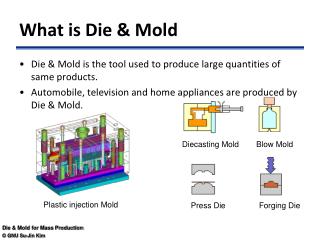
WHAT IS A HPDC DIE. TO FORM A DESIRED SHAPE TO LIQUID ALUMINIUM UNDER HIGH PRESSURE THROUGH A MOLD IS CALLED HPDC DIE.

E N D
WHAT IS A HPDC DIE TO FORM A DESIRED SHAPE TO LIQUID ALUMINIUM UNDER HIGH PRESSURE THROUGH A MOLD IS CALLED HPDC DIE
1.Dies are metallic molds therefore, non-collapsible2. It is costly, both, in terms of time of manufacture and the cost of manufacture3.Its life directly reflects product cost
Why HPDC Die Life is Limited Dies are subject to high clamping/closing loads Working temperatures of all die elements are high Die inserts are vulnerable to stress development at every stage of its service
Expected die life (in its virgin state) is between 80,000 and 100,000 shots
Die Failure Die Failure is a watchword for HPDC! Mechanical Strength required is very high. Thermal conditions are extreme and quick changing. Load-unload situation is mercurial because of very low cycle time. Castings are manufactured under high metal injection load. Engagement and disengagement situation is frequent because of very low cycle time. Surface wear is high. They are subjected to mechanical stresses during manufacture. The casting cycle itself inflicts thermal shocks. The shorter the cycle time, the greater the shock! Closing loads plus casting pressures at high temperature fatigues the die. Meta-stability of heat treatments wears the die due to non-use for sustained period.
Features that Reduce Die Life • Incorrect Die Design • Wrong stipulation of die materials • Inadequate testing of Raw Material • Incorrect Manufacturing Process • Incorrect Heat Treatment Process • Insufficient / incorrect Stress Relief heat treatment • Insufficient Lubrication applied during die operation • Inaccurate cooling of the die during die operation • Lack of timely maintenance
Stress Vulnerability Stages of occurrence: • Manufacture of die • Heat treatment of die • Constant thermal shocking during production from spraying Die Coating to injecting metal at high temperature • Number of shocks are continuous due to fast production • Lack of timely action due to dismal maintenance practice
Importance of Thermal Equilibrium. • All casting dies yield trouble-free output at minimum human effort when working at temperature range of 200-250°C. • Areas forming thick sections may work well at 180-200 °C. and thinner sections at 230-260 °C. • To maintain the differential a simple method has to be perceived viz. heat extraction from the mold wall at a given section. • In GDC process using Cast Iron or Cast Steel molds, a differential wall thickness can be designed in patterns. • In wrought steel molds, calculation is possible!
From this information, it is necessary to highlight effect of each parameter on die life
What action is essential! • Chose the correct material for every die element. • Specify the correct test procedure for material. • Accommodate sufficient thickness for each die element (after cavity carving)! Do not economise! • Specify minimum spark erosion in cavity machining. • Specify correct heat treatments and desired results. • Ensure the results.
Engineering considerations of Die Design. Special attention must be given to each die block thickness available AFTER the cavity is cut. Die block (bottom) thickness is vital considering the thermal condition. Fitment accuracy of bottom block in machine structure Bolt size and quality selection. Guiding tendons for all sliding blocks. Accuracy of pulling centers. Bringing differential draft angles for each die block to (I) facilitate release of casting from mould (II) facilitate smooth ejection.
What is incorrect Die Design? • Inadequate thickness of die inserts • Cooling channels too close to profile • Cooling channels not provided at all • Cooling channels are too small to effect accurate thermal balance • Inadequate wall thickness between cored holes and/or ejector pin holes • Draft angles, for release of casting, are too less • Incorrect dimensional tolerance of the ejector pin hole diameter vis a vis Ejector Pin OD causing either rubbing or aluminum entry • No composite dialogue has taken shape between designer and customer to alter casting profiles to suit sturdy die design • Wrong choice of die material and mechanical strength recommended by designer
Know-how • Every die element has a function to perform. • From the casting (die) inserts to the smallest bolt, all contribute to die life! • Each die element has to have requisite strength. • And that too at elevated temperatures
Effect of wrong stipulation of die materials • Construction of each and every die element is associated with mechanical and metallurgical aspects • Mechanical Engineering aspects decide the strength • Metallurgy provides information on the chemistry of such materials together with the limitation on achievable strength
Effect of wrong stipulation of die materials • Almost all dies fail if the chosen materials are wrong due to lack of metallurgical knowledge • Or when concessions are granted because of cost constraints • Wrong material may not respond to accurate heat treatment parameters, hence erratic strength results
What is preventive measure? Following tests to be conducted to satisfaction BEFORE accepting the raw Material specially the die inserts: • Surface Crack Detection Test • Ultrasound Test • X-ray Test • Chemical Analysis Test
What are these parameters? • Internal flaws • Tensile strength • Wear resistance • Hardness • Fatigue and creep strength.
Milling What to ensure • Accurate speed-feed combination setting. • Use of coolant to avoid spot heating • Depth of cut • Tool path design (in case of CAM) • Post-machining care
Use minimum arc cutting processes • Wire cutting and spark erosion must be utilized sparingly. • Specially, spark erosion! • This must be treated as a finishing operation ONLY!
These processes burn away carbon from the surface of the ferrous die material
Incorrect Heat Treatment Process • This the most likely cause of failure of die inserts • Wrong heat treatment is indicated by: • Material is found harder than the specified higher limit of hardness and needs to be tempered down • Too much scaling (oxidation) is visible on surface • Differential indentation results on different surfaces of the same block
Enhancement of strength of material by a process employing heatWhat are the prerequisites for successful results of Heat Treatment? Die Steels are Cold Rolled Blocks Are you aware of the defects that can occur during Rolling? What is Heat Treatment? ALUCAST
Role of Hardness • Hardness renders • Resistance to closing loads. • Resistance to metal impingement loads. • Resistance to damage due to indentation.
Cold Rolling Defects That Matter • Folding or Shutting • Grain Crushing due to presence of Hard spots • Cracks
All these defects are not visible to the human eye! They can open, split or propagate when heated during Heat Treatments Yet they are difficult to observe after they have split, opened or propagated When these go unnoticed and used in production by HPDC process, they propagate quickly and despite regular stress relieving, the material fails!
Stages at which Stress Relieving is most vital! • When machining is complete* • When Heat Treatment is complete and but prior to taking the die for production • On completing EVERY 30000 to 40000 shots or… • If any repair work, especially welding, is done * Indicates “optional”
Insufficient / incorrect Stress Relief heat treatment • Stresses generate in die materials due to heat and mechanical working • Stress relief treatment is MOST VITAL of all heat treatments in deciding life of a die. We shall see why!
Stages of Stress Generation • At the material supplier’s shop if the sizing is achieved by gas cutting process or worst, Plasma Arc cutting. • While shaving on Shaping Machine • While Milling operation • Heavy stresses are generated on the surface during Spark Erosion • When quenched, post solution heat treatment • After each shot of casting at production stage
Insufficient Lubrication applied during die operation All sliding elements need to be lubricated regularly. These elements are: • Plunger (infrequent lubrication can damage sleeve and bush due to rubbing) • Ejector Pins (assembly) • All guiding pillars and bushes
Inaccurate cooling of the die during die operation • Cooling of dies is a specialized subject • Calculated amount of cooling is a must (calculations are mentioned separately) • Die inserts are overheated if the cooling is too little • Thermal shocking occurs if the cooling is too much
Timely Maintenance as a means of increasing Die Life • Corrective action taken at the first observation is “timely maintenance”! • This action is always a part of production phase
Who observes die wear first? • Die / Machine Operator • Line Inspector, inspecting the castings from production line • Fettling / Trimming operator • Line Inspector, inspecting the castings from fettling line
What to observe? • Plunger sliding action during “shot” • Casting release from fixed half during die opening • Casting release from moving half during die opening • Ejector sliding action during casting removal • Appearance of drag marks on casting • Appearance of heat-checks on casting • Appearance of impression of cracks (veins) on casting surface
What if Plunger slide is erratic? • Clean the plunger “online” of all aluminum flashes • Lubricate the plunger heavily • If the problem persists, replace the plunger and observe sliding • If the problem still persists, STOP! • Check bush and sleeve bores for warp • Check bush and sleeve for cracks by ultrasound testing
Casting Warp during release • Smoothen and polish the areas • Nitride the insert
Ejector sliding action erratic • Clean the pins “online” of all aluminum flashes • Lubricate the pins heavily • If the problem is not sorted, replace the pins and observe sliding • If the problem still persists, STOP! • Check ejector bores in insert for warp • Check concerned areas of inserts for cracks
Appearance of heat-checks on casting • Appearance of heat checks in the die reflect on the casting • These are observed by the line inspector • Heat checks, if ignored, can crack the insert by propagation • Remedy is immediate action • Action is TIG Arcing or Local metal coating
Appearance of impression of cracks (veins) • This indicates that the insert life has neared the end!
What to do next? • Stop production IMMEDIATELY on first observation! • Unload and remove the cracked insert • Test crack depth by ultrasound testing • If the crack depth is 20% or less of the total thickness, open the crack further by grinding and TIG weld to mend it • Match profiles by machining and re-use • DO NOT HEAT TREAT THE INSERT • DO not expect this salvage to last longer than 5000 shots • Plan replacement of insert
To expect highest possible die life discipline in all departments of the organization must function. Work closely, and with all eyes open!