Download
1 / 22
220 likes | 230 Views
CLIC Crab cavity system development. G. Burt, A. Dexter, R. Jones Cockcroft Institute (UK). Crab Cavity Function. Crab cavities are required for ILC, LHC upgrade and CLIC. The crab cavity is a deflection cavity operated with a 90 o phase shift.

E N D
CLIC Crab cavity system development G. Burt, A. Dexter, R. Jones Cockcroft Institute (UK)
Crab Cavity Function Crab cavities are required for ILC, LHC upgrade and CLIC The crab cavity is a deflection cavity operated with a 90o phase shift. A particle at the centre of the bunch gets no transverse momentum kick and hence no deflection at the IP. A particle at the front gets a transverse momentum that is equal and opposite to a particle at the back. The quadrupoles change the rate of rotation of the bunch.
Electric Field in red Beam Magnetic field in green TM110 Dipole mode cavity View from top For a crab cavity the bunch centre is at the cell centre when E is maximum and B is zero
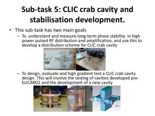
Crab Cavity Issues • Wakefields - cause kicks and emittance growth • Phase Stability - causes kicks Key Required Outcomes 1. Damp, measure and confirm the predicted wakes. 2. Establish feasible/achievable level of phase control performance. (Current requirement is more than ten times state of the art)
Cavity Requirements • Travelling wave cavity at 12 GHz • Damped, detuned structure • Synergy with the main linac • Require 2.4 MV (for R12 = 25 m). • Can achieve a transverse gradient of about 20 MV/m. • This means about 20 cells using a 2pi/3 TW mode. • This requires up to 5 MW of X-band RF.
Wakefields in Crab cavities TM010 accelerating mode Higher order modes TM110v Same order mode Need to extract the fundamental mode TM011 frequency Extraction of the lower order mode and the higher order modes is essential to minimise disruption of the beam. The cavity design should allow for as much LOM/SOM/HOM damping as possible. TE111h TM110h crabbing mode TE111v
Wire tests Our team has significant experience in cold testing cavities, including the ILC crab cavity and the NLC accelerating structures.
electron bunch Δx positron bunch Interaction point LLRF tolerances and system Crabbed crossing angle with phase jitter For a 20 mrad crossing timing tolerance is ~3.5 fs . • Hybrid digital-analogue system • Digital for train to train effect (Synergetic with ILC) • Analogue for fast control • Interferometer required between cavities • Synergetic with ILC development
NLC phase synchronisation proposalNo significant work was undertaken! J. Frisch
Synergy with the ILC Cockcroft funded RA from Nov 07 to work on CLIC Crab Tasks, science and R&D common with ILC funded program Interferometer Klystron modelling Phase control simulation software Some LLRF control hardware Roll tuner Active Feedback on SOM Wire measurements and beadpull Modelling effects in PLACET
Crab Cavity Workplan • Task 1: Cavity and Coupler design and cold test. • Task 2: Phase Control system and interferometer development. • Task 3: Simulate Crab cavity and main linac wakefields. • Task 4: Test cavity at CTF3 at full power with beam.
Kick for 3 TeV CM To minimise required cavity kick R12 needs to be large hence put the cavity close to IP (25 metres suggested) For 20 mrad crossing and using as 12 GHz structure As vertical kicks caused by unwanted modes in the cavity are dangerous one would like R34 to be small.
Key Equations Luminosity reduction factor (Consequence of no crab cavity) Relation between displacement at ip and transverse kick at the crab cavity Kick depends on relative time of arrival t (note voltage kick defined from eV=pc) Displacement for late arrival at time to Kick voltage Vmax required from system to achieve a rotation angle of qris given by
CLIC Crab Cavity Work Plan First objective Establish and verify prototype designs for the CLIC crab cavity system, its high power RF drive, the synchronisation technology. Second objective take a prototype crab cavity system to CTF3, test it operating as part of the linac Third objective Ensure that the system including the crab cavity can continue to meet the luminosity specification taking full account of linac and beam delivery system wakefields. In parallel with this work the means to damp and control wake-fields in the main linac will be explored.
Task 1 - Cavity Development 1.1 Travelling Wave Cavity design 1.2 Input coupler design 1.3 Manufacture and test prototype stacks 1.4 Manufacture and low power tests of full structure Testing includes, cavity tuning, matching couplers and bead pull to determine mode frequencies and field flatness. Our fabrication requirements will be synergetic with the fabrication demands of the main linac and our fabrication effort will be strongly intermeshed with the CLIC main linac development program/team.
Task 2 Wakefield and Beam Dynamic Studies 2.1 Simulation of crab wakefields and design of damping 2.2 Study of manufacturing tolerances on wakefield and phase stability performance 2.3 Beam dynamic simulation and emittance dilution in crab cavity 2.4 Main linac wakefield simulation 2.5 Beam dynamic simulation of emittance dilution and BBU for main linac 2.6 Stretched wire measurements to probe HOMs in the crab cavity and main linac.
Task 3 LLRF development 3.1 Develop phase control concepts. 3.2 Performance simulation of possible CLIC crab cavity LLRF systems. 3.3 Develop and test phase control components. 3.3 Provision of control system for cavities at CTF3.
Task 4 Testing at CTF3 4.1 High power tests on crab cavity 4.2 Measure cavity wakefields (May not be possible at CTF3 but is at ASSeT SLAC) 4.3 Measure deflection of a beam by a single cavity at CTF3 4.4 Test phase stability of two crab cavities (Due in follow on project)
Anticipated Contribution from CERN to collaborate on the iterative design of the X-band accelerating cavities with a view to minimising both electrical breakdown and wake-fields to provide high power RF to drive X band cavities. to provide services such as cooling water for cavity etc.. to install cavity with assistance as required from CI to provide instrumentation on beam to measure deflection