Download
1 / 6
60 likes | 156 Views
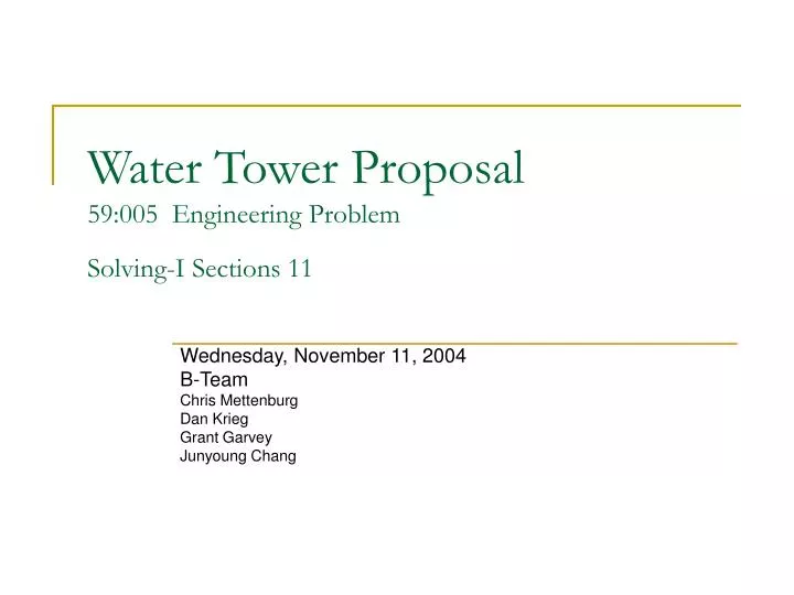
Water Tower Proposal 59:005 Engineering Problem Solving-I Sections 11. Wednesday, November 11, 2004 B-Team Chris Mettenburg Dan Krieg Grant Garvey Junyoung Chang. Build a scale model of a support structure for a water tower calculate loads on the structural members

E N D
Water Tower Proposal59:005 Engineering Problem Solving-I Sections 11 Wednesday, November 11, 2004 B-Team Chris Mettenburg Dan Krieg Grant Garvey Junyoung Chang
Build a scale model of a support structure for a water tower calculate loads on the structural members test the design physically with an initial model modify the design to optimize the performance of final design Our initial testing indicated that our design could hold 47 lbs. without any modifications, so with modification we suspect the model holding 55-65 lbs. Economic Analysis Costs 40 Girders ($1,250 each) =$50,000 56 Short Joints ($350 each) =$19,600 Water Tank =$30,000 Site preparation, water connections, and access =$55,000 Planning =$45,000 Total =$199,600 Objective and Description Receipts
Further Engineering • Further Analysis of Materials • Test different designs • Look at durability and reliability of design • Find the actual limits of the design
Parts – Grooved top and bottom frames Four main support frames. Four extra support frames on each side Sandwich joints Details – Two top and bottom frames were added after the initial model test. Triangle shaped extra support frames. Four sticks combined sandwich joints. Description – Advantage of grooved frame and sandwich joint. Construction Plan 3″ 12″ 4.5″
Force Analysis W W F1 W F3 F3 Θ1 Θ1 Θ2 Inside view of Sandwich Joint Θ3 F4 F1 F5 F4 Θ4 Θ1 Θ5 F6 F5 Θ6 F6 F7 Grooved frame for top and bottom Θ1 • Advantage – Sandwich Joint and grooved frame. • Pass W to the bottom • Disadvantage – X-shaped cross bar & diagonal cross bar F8 F7 Θ7 Θ7 F8 F7 F8