Download
1 / 15
150 likes | 299 Views
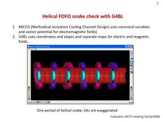
Helical FOFO Snake Update. Y. Alexahin (FNAL APC). 11 th Int. Workshop on Neutrino Factories, Superbeams & Beta Beams, Fermilab/IIT, July 20-25, 2009. Basic Idea. 2. alternating solenoids. absorbers. RF cavities.

E N D
Helical FOFO Snake Update Y. Alexahin (FNAL APC) 11th Int. Workshop on Neutrino Factories, Superbeams & Beta Beams, Fermilab/IIT, July 20-25, 2009
Basic Idea 2 alternating solenoids absorbers RF cavities • The idea: create rotating B field by periodically tilting solenoids, e.g. with 6-solenoid period. • Periodic orbits for μ+ and μ- look exactly the same, just shifted by a half period (3 solenoids). • With tune Q>1 (per period) rD>0 muons with higher momentum make a longer path longitudinal cooling achieved even with planar absorbers B [T] Bx50 Bz By50 z [cm] y x, y [cm] y x x z [cm] Periodic orbit for p=200MeV/c HFOFO Update - Y. Alexahin NUFACT09, IIT Chicago July 22, 2009
Why double cavities? 3 solenoids Double cavity increases packing factor w/o reduction in the transit factor Hopefully the breakdown RF gradient will not be much reduced due to magnetic field with such configuration HFOFO Update - Y. Alexahin NUFACT09, IIT Chicago July 22, 2009
Beta-functions & tunes 4 x y Solenoids: L=24cm, Rin=60cm, Rout=92cm, pitch 7mrad, Bzmax=2.35T (p=200MeV/c) RF: 200 MHz pillbox 2x36cm, Emax=16MV/m Absorbers: 15cm LH2 planar at the absorber locations < > ~ 70cm - compare with MICE’s < > ~ 45cm The best results with 7mrad pitch angle, no absorber wedge angle: mode I II III tune 1.239+0.012i 1.279+0.007i 0.181+0.002i _eq (mm) 3.2 4.5 6.9 ImQ=0.007 cooling rate d log / dz = 22/L ImQ = 1/70m Bmax=2.3T j=58A/mm^2, Itot=4.4MA/solenoid There is difficulty in equalization of damping rates of the transverse modes HFOFO Update - Y. Alexahin NUFACT09, IIT Chicago July 22, 2009
Tracking with MICCD 5 • “True” action variables of 1771 particles evenly distributed in tetrahedron (JI + JII)/2.6 + JIII /4 < 1 (cm) • Phases chosen at random • No decay or stochastic processes Courant-Snyder invariant =2J, to compare with normalized emittance multiply by 2: CSImax10cm or 2.2 for N=2cm canonical momenta (include vector-potential), p0=200MeV/c Py/p0 p Px/p0 x [cm] y [cm] z-v0t blue - initial, red – after 25 periods (153m) HFOFO Update - Y. Alexahin NUFACT09, IIT Chicago July 22, 2009
Tune “repulsion” from integer resonance 6 no absorber, no RF QI, II Nice surprise: Large 2nd order chromaticity due to nonlinear field components keeps both tunes from crossing the integer ! p/200 orbit length/L0 Momentum compaction factor: - in contrast to classical HCC with homogeneous absorber where to ensure longitudinal damping. p/200 HFOFO Update - Y. Alexahin NUFACT09, IIT Chicago July 22, 2009
Excursion - Longitudinal Hamiltonian 7 K URF =0.007 =0.014 p p -0 (rad) Kinetic energy in quasi-static approximation Contour plot of the longitudinal Hamiltonian for =0.014 - kinematic nonlinearity limits momentum acceptance, not insufficient RF bucket depth. where = orbit length/L0 Longitudinal separatrix reaches maximum at 0.007 HFOFO Update - Y. Alexahin NUFACT09, IIT Chicago July 22, 2009
Tracking with G4BL 8 (p-p0)/p0 px/p0 py/p0 x [cm] t [ns] y [cm] Stochastic processes on, but no decays mechanical momenta, p0=200MeV/c blue - initial (the same ensemble), red – after 20 periods (122m) HFOFO Update - Y. Alexahin NUFACT09, IIT Chicago July 22, 2009
Analysis of G4BL Tracking Data 9 N/N0 no decays! With decays transmission over 20 periods (122.4m) is > 85% Initial/final N [cm]=1.7, 1.8, 2.1 / 0.37, 0.7, 1.1 6D cooling efficiency (following R.Palmer’s definition) Q6 20 G4BL stochs. off MICCD G4BL stochs. on Transmission vs period # N [cm] Recipe for emittance calculation: compute normal mode amplitudes am for each muon using lattice eigenvectors subtract average values find distribution in action variables Jm =| am |2 fit with exponential function 3N 2N 1N Normal mode emittances (normalized) vs period # (_eq = 0.32, 0.45, 0.69) multiply m by 00 HFOFO Update - Y. Alexahin NUFACT09, IIT Chicago July 22, 2009
Equalization of transverse modes damping rates 10 y x z N/N0 period # R. Palmer proposedto add ~ constant solenoidal field to better mix the transverse modes and equalize their damping rates. This can be achieved by powering e.g. negative solenoids with slightly lower current. With just (I+ - I-)/ I+ = 1.6% : mode I II III tune 1.211+0.0100i 1.301+0.0108i 0.196+0.0003i _eq (mm) 3.8 3.2 36.5 (fast transverse cooling w/o longitudinal blowup was the intent): Unfortunately, there is no appreciable gain in equilibrium emittance due to large -wave excited with unequal field in + and - solenoids. Transmission also suffers (red vs. blue) - computed without stochastic effects and decay HFOFO Update - Y. Alexahin NUFACT09, IIT Chicago July 22, 2009
Damping Rate Equalization with Quadrupole Field 11 y (cm) Dy (cm) Dx (cm) z x (cm) z Most efficient “equalizer” is constant quadrupole field superimposed on the main solenidal field. With a gradient of just 0.057 T/m: mode I II III tune 1.240+0.0088i 1.286+0.0087i 0.178+0.0036i _eq (mm) 3.9 3.8 4.7 (w/o quad was 3.2 4.5 6.9) The sum of betas smaller - no increase in transverse emittance (despite smaller long. emittance) 50% stronger long. damping due to larger dispersion (smaller solenoid pitch required) The effect does not depend on quad tilt (and polarity) as well as on the muon sign - the channel is still good for both! HFOFO Update - Y. Alexahin NUFACT09, IIT Chicago July 22, 2009
G4BL Simulations with Quad “Equalizer” 12 N/N0 with quad 3N 1N with quad w/o quad 2N period # period # w/o quad Initial / final emittances (cm) with quad: 3N 1.71, 1.79, 2.20 / 0.554, 0.584, 1.006 2N w/o quad: 1N 1.66, 1.80, 2.05 / 0.367, 0.701, 1.096 There is not so much reduction in final emittances due to the damping rate equalization as increase in the initial values due to changes in nonlinear transformation from “true” normal forms period # (Here emittances in cm) HFOFO Update - Y. Alexahin NUFACT09, IIT Chicago July 22, 2009
Absorber Container and RF Cavity Walls 13 A MODERN AIRCRAFT ALUMINUM ALLOY (thanks to Don Summers) Aluminum Alloy Yield Tensile Radiation Name Composition Density Strength Strength Length % by weight g/cc ksi ksi cm 300K 300K 20K 6061-T6 1.0Mg .6Si .3Cu .2Cr 2.70 40 45 68 8.86 2090-T81 2.7Cu 2.2Li .12Zr 2.59 74 82 120 9.18 Supposedly 2090-T81 walls can be made 0.1mm thick (as compared to 0.18mm of 6061-T6 in MICE). Three cases considered below: No container nor cavity walls (original lattice) Two 0.1mm 2090-T81 container walls / absorber, no safety walls nor cavity walls Two 0.1mm 2090-T81 container walls / absorber + three 0.38mm Be walls / two RF cavities Q1 Q2 Q31N (mm) 2N (mm) 3N (mm) ERF (MV/m) No walls 1.239+0.012i 1.279+0.007i 0.181+0.0025i 3.2 4.5 6.9 16.0 Abs. walls 1.241+0.012i 1.281+0.007i 0.185+0.0026i 3.7 5.1 7.5 16.3 + RF walls 1.243+0.013i 1.286+0.007i 0.191+0.0033i 4.0 5.8 7.3 17.5 Though the effect of the walls is tolerable (<30% increase in the equilibrium emittance) it would be worth while to look for a lighter material for the absorber walls (Be?) HFOFO Update - Y. Alexahin NUFACT09, IIT Chicago July 22, 2009
G4BL Simulations with Walls 14 3N 2N 1N period # N/N0 w/o walls with walls period # Final emittances for the cases 1 and 3: 1N (mm) 2N (mm) 3N (mm) 6D (mm^3) No walls 3.67 7.01 10.96 218.2 With all walls 3.63 7.77 10.22 212.9 - Strange result, may be due to a faster cooling with 9% increase in losses and the RF gradient HFOFO Update - Y. Alexahin NUFACT09, IIT Chicago July 22, 2009
Summary & Outlook 15 Tilting solenoids of ASOL channel (Dave’s nomenclature) increases momentum acceptance and provides some longitudinal cooling with only mild deterioration of transverse acceptance and cooling (look for the optimum!) Transverse damping rates can be equalized by adding quadrupole field without compromising transverse or momentum acceptance HFOFO with 200MHz double RF gives T < 6mm, L ~10mm Another 200MHz section with single RF can give T ~ 3mm, L ~10mm Combine HFOFO cooling with Daves bunching / rotation Higher phase advance per cell small betas @ absorbers Better options for the absorber and RF cavity windows? HFOFO Update - Y. Alexahin NUFACT09, IIT Chicago July 22, 2009