Download
1 / 46
690 likes | 1.38k Views
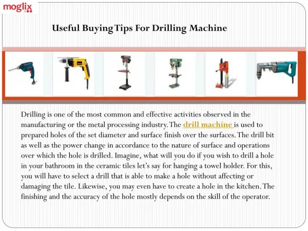
DRILLING MACHINE. DRILLING. Drilling is a metal cutting process carried out by a rotating cutting tool (twist drill) to make circular holes in solid materials. Drilling Machine. A power operated machine tool, which holds the drill in its rotating spindle and produces a hole when

E N D
DRILLING MACHINE Dept. of Mech & Mfg. Engg.
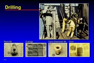
DRILLING Drilling is a metal cutting process carried out by a rotating cutting tool (twist drill) to make circular holes in solid materials. Dept. of Mech & Mfg. Engg.
Drilling Machine A power operated machine tool, which holds the drill in its rotating spindle and produces a hole when moved linearly against the work piece. Dept. of Mech & Mfg. Engg.
Twist Drill Dept. of Mech & Mfg. Engg.
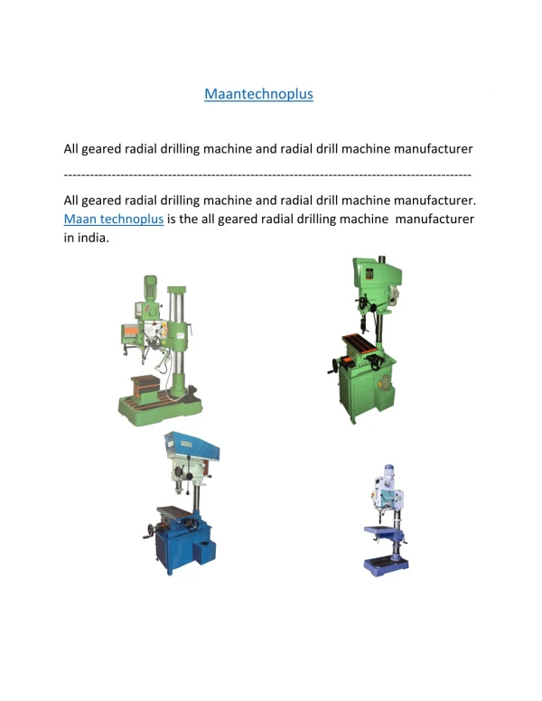
Types of Drilling Machines Drilling machines may be classified as • BenchorSensitive drilling machine. • Radial drilling machine. Dept. of Mech & Mfg. Engg.
BENCH DRILLING MACHINE Dept. of Mech & Mfg. Engg.
Bench Drilling Machine Dept. of Mech & Mfg. Engg.
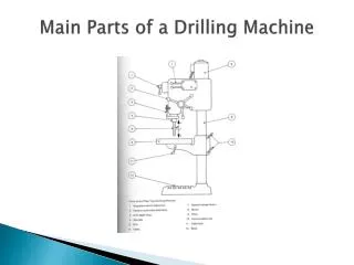
Bench Drilling Machine • Located generally on the work bench • Used for small jobs, also called as sensitive drilling machine. • Used for drilling small and medium sized holes (up to 15mm ). • Consists of a round column with a rigid base fastened to the bench • Has a work holding table and an arm mounted on the round column • Arm carries the drill spindle on one side and the drive motor on the other side • A stepped cone pulley with V – belt is used to transmit the power from motor to spindle Dept. of Mech & Mfg. Engg.
Bench Drilling Machine • The work table can be moved up and down to suit the required job height and can be locked at suitable height • The table can rotate about its axis by 360° • Drilling operation is performed by fixing the job properly on the work table • Drill bit is gradually fed by rotating hand feed lever towards the work piece • Once the required depth of cut is completed, the feed lever is rotated in the opposite direction to withdraw the tool from the work. Dept. of Mech & Mfg. Engg.
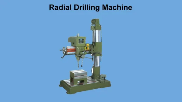
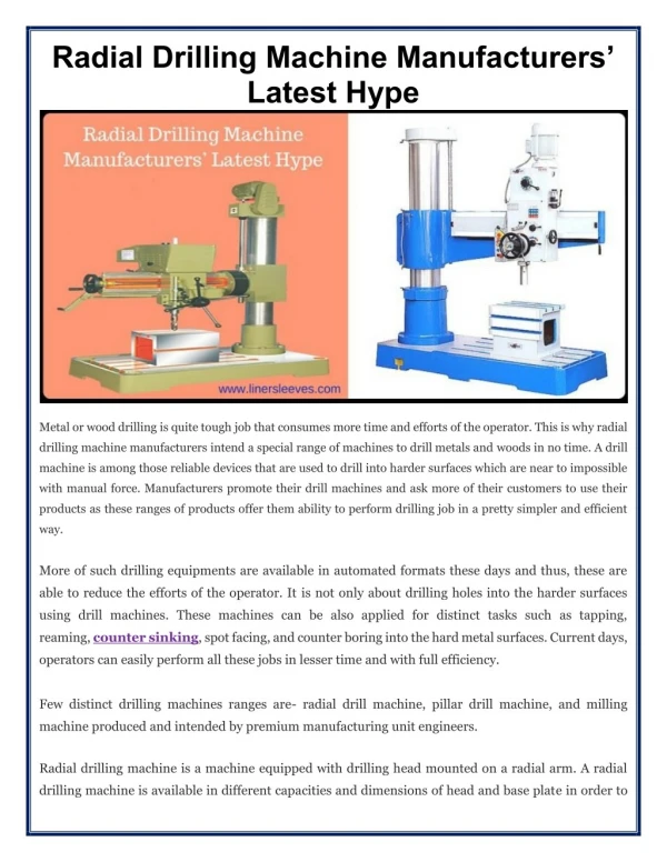
Radial Drilling Machine Dept. of Mech & Mfg. Engg.
Radial Drilling Machine • Radial drilling machine is used for medium and heavy duty applications • Consists of a heavy, circular column mounted on a very strong base • Radial arm that can swing around is mounted on the column and the radial arm can be raised and lowered • Drill head with drive and feed mechanism is fitted on to the radial arm • Drill head can move horizontally along the guides of the arm and can be locked at any desired position Dept. of Mech & Mfg. Engg.
Types of Drilling Machines Drilling machines may be classified as • Portable drilling machine. • BenchorSensitive drilling machine. • Radial drilling machine. • Pillar drilling machine. • Gang drilling machine. • Multiple spindle drilling machine. Dept. of Mech & Mfg. Engg.
List the operation performed on a drilling machine. The different machining operations that can be performed on a drilling machine are as follows. • Drilling • Reaming • Boring. • Counter Boring • Counter sinking • Spot facing • Tapping. Dept. of Mech & Mfg. Engg.
Boring: • Done on a drilling machine to • increase the size of an • already drilled hole • When a suitable size drill is not • available, • Initially a hole is drilled to the nearest size • Using a single point cutting tool, the size of the hole is increased to required size By lowering the tool while it is continuously rotating, • The size of the hole is increased to its entire depth. Dept. of Mech & Mfg. Engg.
Counter bore Tool Pilot • Counter boring • It is to increase the size of a hole at one end only through a small depth • It forms a larger sized recess or a shoulder to the exiting hole • The cutting tool will have a • small cylindrical projection • known as pilot • It guides the tool Dept. of Mech & Mfg. Engg.
Counter bore Tool Counter boring Pilot Condition: • Diameter of the pilot will always be equal to the diameter of the previously drilled hole Cutting Speed: • Two-third of the drilling speed Purpose: It is done on the hole to accommodate the socket head screw, or grooved nuts, or round head bolts. Dept. of Mech & Mfg. Engg.
Countersinking It is the operation of making the end of the hole into a conical shape • Using countersinking tool • May also be employed for deburring the holes Cutting speed One - half of that used for similar size drill Use: When the countersunk screws are to be screwed into the holes, so that their top faces have to be in flush with the top surface of the work piece. Dept. of Mech & Mfg. Engg.
Drilling Operations Dept. of Mech & Mfg. Engg.
Milling Machine • Milling is a metal cutting operation in which the operating tool is a slow revolving cutter having cutting teeth formed on its periphery. • The milling cutter is a multipoint cutting tool. The work piece is mounted on a movable work table which will be fed against the revolving milling cutter to perform the cutting operation.
The difference between drilling and milling is that, in drilling a rotating drill is fed against a stationary work-piece, while in milling the work-piece is fed against a milling cutter which only revolves. • Similarly, it also differs from the lathe operation because the lathe tool is fed against rotating work-piece. • A milling machine is a power operated machine tool in which the work-piece mounted on moving table is machined to various shapes when moved under a slow revolving serrated cutter.
Principle of Milling • The Figure 1 shows the principle of cutting action of the milling cutter. The milling cutter is mounted on a rotating shaft known as arbor. The work-piece which is mounted on the table can be fed either in the direction opposite to that of the rotating cutter as shown in Fig.1A or in the same direction of that of the cutter as shown in Fig.1B.
When the work-piece is fed in the opposite direction to the cutter tooth at the point of contact, the process is called conventional or up milling. • In this process, as the work-piece advances against the rotating cutter, the chip that is removed gets progressively thicker as shown in Fig.1A
The action of the cutter forces the work-piece and the table against the direction of the table feed, thus each cutter tooth enters a clean metal gradually thus the shock load on each tooth is minimized. • The disadvantage of this method is that when making deep cuts, such as in heavy slotting operations, the cutter tends to pull the work-piece out of the vice or the fixture since the cutting force is directed upward at an angle.
When the work-piece is fed in the same direction as that of the cutter tooth at the point of contact, as shown in Fig. 1B, the process is called climb or down milling. • In this process, the cutter enters the top of the work-piece and removes the chip that gets progressively thinner as the cutter tooth rotates.
Generally, more metal can be removed for each cut than the conventional up milling. Climb milling is used only on materials that are free of scale and other surface imperfections that would damage the cutters. • Classification of Milling Machine • Plain or Horizontal Type of Milling Machine • Vertical Milling Machine • Universal Milling Machine • Planer Type Milling Machine • Profile Cutting Milling Machine
SHAPER • The shaper is a reciprocating type of machine tool intended primarily to produce flat surfaces. • These surfaces may be horizontal, vertical, or inclined. • In general shaper can produce any surface composed of straight line elements.
Ram: it holds and imparts cutting motion to the tool through reciprocation • Bed: it holds and imparts feed motions to the job • Housing with base: the basic structure and also accommodate the drive mechanisms • Power drive with speed and feed change mechanisms. • Shaping machines are generally used for producing flat surfaces, grooving, splitting etc. • Because of poor productivity and process capability these machine tools are not widely used now-a-days for production.
Grinding, also called abrasive machining, is a process in which the material is removed in the form of fine chips, almost as dust particles by the abrasive action using some kind of abrasive materials. • The thickness of the material chips removed by grinding ranges from 0.25 to 0.50 mm in finishing and general grinding operations. • Abrasive is the mineral material employed for sharpening, grinding and polishing operations
The two types of abrasives used are; natural and artificial. • The examples of natural abrasives are emery, corundum, quartz. sandstone, diamond, etc. • The important properties of abrasives are, hardness, toughness, uniformity in grain sizes, and sharpness.
Grinding wheel Terminology • Grit • The grit is the grain size of the abrasive grain. • The grain size is expressed as a number. Thus, coarse grain size can be between 10 and 24, Medium grain size can be between 30 & 60, Fine grain size can be between so and, very fine grain size can be between 220 and 600.
Grade • Grade is the hardness of the bond, which is designated by alphabets. The letter "A" Stands for very soft material and the letter " Z" stands for very hard grade. • Wheel structure • The abrasive grains are distributed over the abrasive wheel in a structural form. The wheel structure is also represented as a number. For example, Dense can be from 1 to 8 and Open can be from 9 to 15.
Bond type • It is denoted by alphabets like V is for vitrified Bond, B is for Resinoid, R is for Rubber, E is for shellac and S is for silicate, and so on. • Abrasive • Abrasives are denoted by alphabets-Example: A stands for Aluminum oxide & C Stands for Silicon Carbide.