Download
1 / 16
160 likes | 245 Views
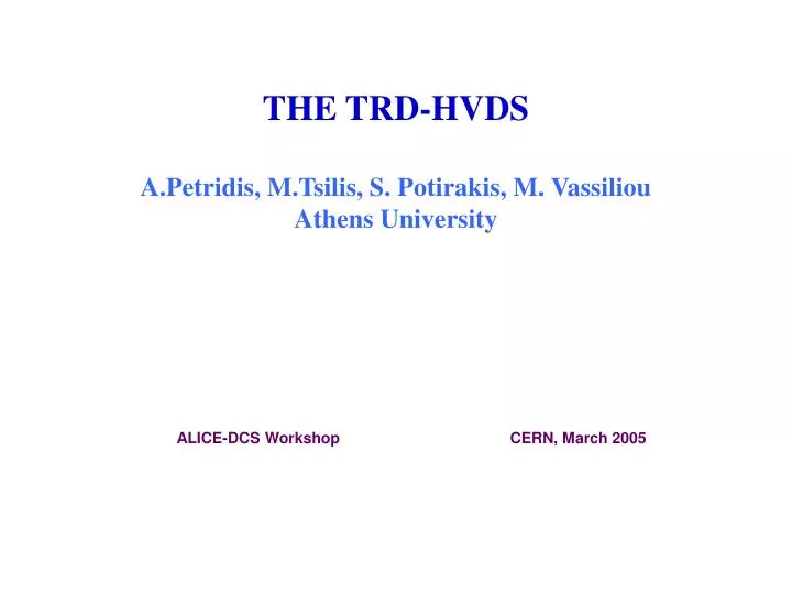
THE TRD-HVDS A.Petridis, M.Tsilis, S. Potirakis, M. Vassiliou Athens University. ALICE-DCS Workshop CERN, March 2005. INTRODUCTION.

E N D
THE TRD-HVDS A.Petridis, M.Tsilis, S. Potirakis, M. VassiliouAthens University ALICE-DCS Workshop CERN, March 2005
INTRODUCTION • We have designed a Master/Slave power supply distribution system to provide the required anode and drift voltage to the ALICE TRD readout chambers. • The system will be used to switch on and off, monitor (on the nA level) and regulate (leverage of 100-150V in steps of 1V from a common ceiling voltage).
Requirements (i)The anode wires plane of each chamber will be supplied with HV independently. The total number of individual HV channels is 540. • The required anode wire voltage is around 1.6 – 1.7 KV in order to reach the required gas gain. • The ripple should be smaller than 50mV peak to peak and the stability better than 0.1% over 24hours. • The maximum aloud current in a single chamber is set to ~7μA and the current will be monitored with an accuracy of nAlevel.
(ii) In order to create the necessary drift field of negative 2.1-2.9KV is needed to be supplied independently to each chamber. The total number of individual HV channels is also 540. The ripple should be smaller than 50mV peak to peak and the stability better than 0.1% over 24 hours. The drift field current of a single chamber will measured with an accuracy of 40 nA and the aloud maximum drift field current is set to ~170μA.
MAIN COMPONETS Master Voltage where a nominal ceiling voltage is provided to the Slave system Reed Relay to switch on-off the power to the 6! number of channels Reed Relay to switch on-off the power to a single chamber LOW VOLTAGE SITE COMPONENTS Shunt Regulator (H.V transistor Adder amplifier, Error amplifier and a switching off transistor! High Accuracy Voltage Divider(~500MOhm 24 bit 6# ΣΔADC for measuring the output voltage 12 bit 6# DAC system for biasing the two transistors in (3) Microcontroller Auxiliary power supply HIGH VOLTAGE SITE COMPONENTS Current Sensing Resistor High precision Ultra Low noise and input current amplifiers Single 24 bit ΣΔADC 3in+3out Optoisolators Auxiliary power supply per channel Comparator for tripping conditions with optoiolators.
Organization The system is divided to the sub-projects: • Analog part (op,dac,adc, auxiliary supplies…) • Digital part (CANBUS, μC) • Embedded Software • Communication software
Subsystem ADS’s(analog) The following 24bit ΔΣADS’s were proposed and tested: • Analog Devices AD7731 on the board. Rejected • Texas Instrument ADS1224 14 bit accuracy not programmable • Texas Instrument ADS1243 Just Acceptable 15bit prog. ~20Hz • Texas Instrument ADS1256 Under Investigation • Linear Technology LTC12449 Under Investigation Subsystem DAC (analog) Tested MAX5306/12bit, 8# Good but just ~1V step
Reed relays • The 5 KV (3KV switching) reed relay functions normally up to 50 Gauss. • The 3KV (1KV switching) up to 20 Gauss. Hence both relays need a Faraday cage. This can be done either at the level of card or at the level of crate or rack.
Two low current low noise and one differantial instrumentation amplifiers AD8628 against OP297 Single differential amplifier Two topologies for current measurement INA111 INA106
μController The Mega16 of the AVR family may be the final μC. Embedded software has been developed for controlling the active parts af the system. No problem of programming. We have to improve and optimize the software during the time of developing the system.
Digital Part Support: • STK500 evaluation boards for AVR μC. 10 Mega16 and Mega8 μControllers. 10 Canbuses SJA1000 with their transceivers. • Candip board (SJA1000 controller + mega162) 1 Canbus Evaluation Board.
What we have done so far We have designed and constructed PCB cards, with all the components on it, for 6 different current monitoring topologies. (4 layers) Also auxiliary power supply board was designed and build in order to provide power to both To the high voltage stand components and to the low one. (2 layers) In order 1.To choose the most appropriate topology. 2.To validate the choice of the components. 3. To measure the power consumption of the system in order to improve the designed auxiliary power supply. 4. To develop the first level communication software between the local μController and the active components.
To DO (lead free!!) • New design, construction and test of the auxiliary power supplies. • New design,construction and debbuging one/two boards with 6 channels. To be tested in the next TRD test beam. • Design , construction and debbuging the total digital system. (canbus + microcontrollers) • System Integration • Mechanical design (accuray of card size and backplane external connector, possible field isolation, connectors, spacers etc. ) • Order of components.
CANBUS communication system μC CAN μC μC One canbus (CAN+μC) can control N μC Each μC can drive M cards with 6# each Total No of cards = N*M N=8 M=6 Total=48 cards ~ 3 crates μC