Download
1 / 23
270 likes | 503 Views
Camera Link Communication Interface for Vision Applications. J. Egri 6/7/05. Background. Prior to Camera Link, there were a number of non-standard parallel interfaces using either LVDS or RS422 signaling Different connectors and pinouts made cable production difficult and confusing

E N D
Camera Link Communication Interface for Vision Applications J. Egri 6/7/05
Background • Prior to Camera Link, there were a number of non-standard parallel interfaces using either LVDS or RS422 signaling • Different connectors and pinouts made cable production difficult and confusing • No standard communications method for configuring cameras existed
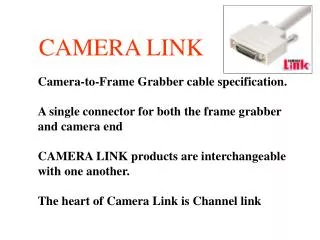
Camera Link was developed in 2000 by an industry consortium of camera and frame grabber companies • Defines a connectivity standard between digital cameras and frame grabbers • Ensures that all Camera Link products are interchangeable and interoperable • de Facto standard for high speed/high resolution imaging
Overview • Based on the field proven Channel Link technology developed for flat panel displays • Utilizes LVDS signaling providing higher speed, lower power and greater noise immunity • Transports synchronous digital video data and clock, a bi-directional communications channel and 4 discrete general purpose signals • Camera Link reduces the number of signals required allowing for smaller, more reliable and lower cost cables • Uses one ( for Base mode ) or two ( for Medium or Full mode ) 26 pin connectors
Channel Link consists of a driver and receive pair • Driver accepts 28 bit single ended data plus a clock • The 28 bit data includes 24 bits of video data plus 4 strobes ( FVAL, LVAL, DVAL and spare ) • Data is multiplexed 7:1 and serialized • The resulting 4 data streams plus clock are driven out over 5 LVDS pairs • Clock rate is from 20 to 85 MHz • Yields up to 2.04 Gbps ( 24 bit video data * 85 MHz ) • Cable length is 10 Meters maximum
Camera Link Interface • Uses Channel Link for video data, strobes and clock • Uses an additional LVDS receiver and driver for a bi-directional asynchronous communications channel • Uses 4 additional LVDS pairs for 4 discrete general purpose camera control signals • Provides 3 modes: Base, Medium and Full
Base mode: • one Channel Link interface • one connector • 24 bit video data • up to 2.04 Gbps aggregate bandwidth • Medium mode: • two Channel Link interfaces • two connectors • 48 bit video data • up to 4.08 Gbps aggregate bandwidth • Full mode: • three Channel Link interfaces • two connectors • 64 bit video data • up to 5.44 Gbps aggregate bandwidth
G R A B B E R C A M E R A F R A M E Base Mode
G R A B B E R C A M E R A F R A M E Medium Mode
G R A B B E R C A M E R A F R A M E Full Mode
Strobes • FVAL ( Frame Valid ) - envelopes all lines in a frame • LVAL ( Line Valid ) - envelopes all pixels in a line • DVAL ( Data Valid ) - qualifies valid pixels in a line
Communications Channel • Used to configure camera’s operating parameters • On the Imperx Lynx cameras: Also used to upload new firmware, software and lookup tables into the camera • Two LVDS signals for asynchronous serial communications • Frame Grabber–to–Camera communications • Camera–to–Frame Grabber communications • ASYNC format : 1 start, 8 data bits, 1 stop, 0 parity, no handshaking • BAUD rates : 9600 bps to 115.2 Kbps • Standard API using clser***.dll ensures interoperability between camera configuration software and frame grabber
Camera control viaGUI Example from Imperx Lynx Configurator camera utility
Camera control viaTerminal Example from Imperx LynxTerminal camera utility
Camera download Example from Imperx LynxTerminal camera utility
Camera Control signals • 4 general purpose camera control signals ( CC1-CC4 ) • Driven by the Frame Grabber to the Camera • Use is defined by the camera vendor • Often used as a software trigger • Often used to control the camera exposure Example from Imperx FrameLink frame grabber
Advantages of Camera Link • Industry tested and proven technology • Easy camera/frame grabber integration • Camera Link products are interchangeable and interoperable • Standardized DLL based API for camera configuration • Higher bandwidth and lower latency than competing interfaces • Point-to-point interface yields deterministic data transfer rate • Full use of available bandwidth for payload. No protocol overhead or encapsulation penalty • Processing can be performed in frame grabber hardware rather than by CPU ( i.e. Bayer interpolation, table look up, frame averaging, pixel reordering, etc. )
Image is DMA’ed directly into system or video memory by the frame grabber freeing up the CPU • Multiple cameras processed on frame grabber ( i.e. Zygo uses four Lynx cameras operating at 210 fps each for flat panel inspection ) • Embedded serial communications channel for camera configuration • Embedded discrete camera control signals • Comprehensive set of video data modes supported • Connectors, data format and control signals are all standardized • Smaller cable size improves reliability and reduces cost • Industry standard cable results in competitive pricing
Disadvantages of Camera Link • Cable length is limited to 10 meters. This can be solved by using repeaters ( such as the Imperx model CLCL ) or fiber converters • Requires a frame grabber • Power is not supplied over the Camera Link cable and therefore cameras require a second connector for power
Why Imperx chose Camera Link • We use high resolution Kodak CCD sensors which produce large video payloads and require high bandwidth transport • Our customers demand low latency response for real time applications Note: Bandwidth listed is 80% of the theoretical maximum
Future of Camera Link • New specification v1.1 ratified by AIA • Adds additional functionality to the clser***.dll API for the serial interface • Provides reference source code to committee members • New draft in development: • Adds additional video modes • Introduces Honda miniature Camera Link connector • Introduces new smaller diameter cable ( 28 vs. 26 gauge conductors ) • Adds ‘power over cable’ capability