Download
1 / 71
710 likes | 817 Views
Chapter 8 TCP/IP. Chapter Figures. Application. Application. TCP. UDP. ICMP. IP. ARP. RARP. Network interface. Figure 8.1. HTTP Request. Header contains source & destination port numbers. TCP header. Header contains source and destination IP addresses; transport protocol type.

E N D
Chapter 8TCP/IP Chapter Figures
Application Application TCP UDP ICMP IP ARP RARP Network interface Communication Networks Figure 8.1
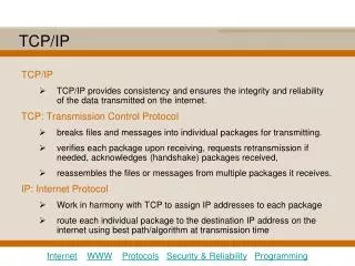
HTTP Request Header contains source & destination port numbers TCP header Header contains source and destination IP addresses; transport protocol type IP header Header contains source & destination physical addresses; network protocol type Ethernet header FCS Figure 8.2 Communication Networks
Machine B Machine A Application layer Application layer Router/gateway Transport layer Transport layer Internet layer Internet layer Internet layer Networkinterfacelayer Network interface layer Network interface layer Network 1 Network 2 Figure 8.3 Communication Networks
0 4 8 16 19 24 31 Version IHL Type of service Total length Identification Flags Fragment offset Time to live Protocol Header checksum Source IP address Destination IP address Options Padding Figure 8.4 Communication Networks
Figure 8.5 Communication Networks
Bit position: 0 1 2 3 8 16 31 Class A 0 Net ID Host ID Class B 1 0 Net ID Host ID Class C 1 1 0 Net ID Host ID Class D 1 1 1 0 Multicast address Class E 1 1 1 1 Reserved for experiments Figure 8.6 Communication Networks
Original 1 0 Net ID Host ID address Subnetted 1 0 Net ID Subnet ID Host ID address Figure 8.7 Communication Networks
H1 H2 150.100.12.154 150.100.12.176 150.100.12.128 150.100.12.129 150.100.0.1 R1 To the rest of H3 H4 150.100.12.4 the Internet 150.100.12.55 150.100.12.24 150.100.12.0 150.100.12.1 R2 H5 150.100.15.54 150.100.15.11 150.100.15.0 Figure 8.8 Communication Networks
H1 H2 H3 H4 150.100.76.22 150.100.76.23 150.100.76.20 150.100.76.21 ARP request (what is the MAC address of 150.100.76.22?) H1 H2 H3 H4 ARP response (my MAC address is 08:00:5a:3b:94) Figure 8.9 Communication Networks
Figure 8.10 Communication Networks
Source Router Destination IP IP Network Network Figure 8.11 Communication Networks
0 8 16 31 Type Code Checksum Unused IP header and 64 bits of original datagram Figure 812 Communication Networks
0 8 16 31 Type Code Checksum Identifier Sequence number Data Figure 8.13 Communication Networks
Figure 8.15 Communication Networks
Figure 8.15 Communication Networks
0 4 12 16 24 31 Version Traffic class Flow label Payload length Next header Hop limit Source address Destination address Figure 8.16 Communication Networks
Figure 8.17 Communication Networks
n bits m bits o bits p bits (125-m-n-o-p) bits 010 Registry ID Provider ID Subscriber ID Subnet ID Interface ID Figure 8.18 Communication Networks
Basic header Next header = TCP segment TCP Basic header Routing header Fragment header Authentication header Next header = Next header = Next header = Next header = TCP segment routing fragment authentication TCP Figure 8.19 Communication Networks
0 8 16 24 31 Next header 0 194 Opt len = 4 Jumbo payload length Figure 8.20 Communication Networks
0 8 16 29 31 Next header Reserved Fragment offset Res M Identification Figure 8.16 Communication Networks
0 8 16 24 31 Next header Header length Routing type = 0 Segment left Reserved Strict/loose bit mask Address 1 Address 2 . . . Address 24 Figure 8.22 Communication Networks
Tunnel tail-end Tunnel head-end Destination Source Tunnel (a) IPv6 header IPv4 header IPv6 network IPv6 network IPv4 network Destination Source Link (b) IPv6 network IPv6 network Figure 8.23 Communication Networks
0 16 31 Source Port Destination Port UDP Length UDP Checksum Data Figure 8.24 Communication Networks
0 8 16 31 Source IP address Destination IP address 0 0 0 0 0 0 0 0 Protocol = 17 UDP length Figure 8.25 Communication Networks
Application Application byte stream byte stream Segments Transmitter Receiver Receive buffer Send buffer ACKs Figure 8.26 Communication Networks
0 4 10 16 24 31 Source port Destination port Sequence number Acknowledgment number U A P R S F Header R C S S Y I Reserved Window size length G K H T N N Checksum Urgent pointer Options Padding Data Figure 8.27 Communication Networks
0 8 16 31 Source IP address Destination IP address 0 0 0 0 0 0 0 0 Protocol = 6 TCP segment length Figure 8.28 Communication Networks
Host A Host B SYN, Seq_no = x SYN, Seq_no = y, ACK, Ack_no = x+1 Seq_no = x+1, ACK, Ack_no = y+1 Figure 8.29 Communication Networks
Host A Host B SYN, Seq_no = n, ACK, Ack_no = n+1 Seq_no = n+1, ACK, Ack_no = n+1 Delayed segment with Seq_no = n+2 will be accepted SYN, Seq_no = n Figure 8.30 Communication Networks
Figure 8.31 Communication Networks
Host B (server) Host A (client) socket bind listen accept(blocks) t1 socket connect (blocks) SYN, Seq_no = x t2 SYN, Seq_no = y, ACK, Ack_no = x+1 connect returns t3 Seq_no = x+1, ACK, Ack_no = y+1 write read (blocks) accept returns read (blocks) t4 t5 Request message read returns t6 write read (blocks) Reply message read returns Figure 8.32 Communication Networks
Host A Host B t0 Seq_no = 1, Ack_no = 2000, Win = 2048, No Data t1 Seq_no = 2000, Ack_no = 1, Win = 1024, Data = 2000-3023 t2 Seq_no = 3024, Ack_no = 1, Win = 1024, Data = 3024-4047 t3 Seq_no = 1, Ack_no = 4048, Win = 512, Data = 1-128 t4 Seq_no = 4048, Ack_no = 129, Win = 1024, Data = 4048-4559 Figure 8.33 Communication Networks
Data Header contains source and destination port numbers TCP Header Header contains: source and dest. IP addresses; transport protocol type IP Header Figure 8.34 Communication Networks
Host A Host B FIN, seq = 5086 Ack = 5087 Data, seq. = 303, Ack=5087 Deliver 150 bytes Ack = 453 FIN, seq. =453, Ack = 5087 Ack = 454 Figure 8.35 Communication Networks
CLOSED Appli-cation close passive open, create TCB active open, create TCB send SYN LISTEN receive SYN, send SYN, ACK receive RST send SYN application close or timeout, delete TCB receive SYN, send ACK SYN_SENT SYN_RCVD receive SYN, ACK, send ACK receive ACK application close, send FIN ESTABLISHED receive FIN, send ACK application close, send FIN CLOSE_WAIT receive FIN send ACK application close send FIN CLOSING FIN_WAIT_1 receive ACK LAST_ACK receive ACK receive ACK receive FIN, ACK send ACK receive FIN send ACK 2MSL timeout delete TCB FIN_WAIT_2 TIME_WAIT Figure 8.36 Communication Networks
Congestion avoidance 20 Time-out 15 Threshold Congestion window 10 Slow start 5 0 Round-trip times Figure 8.37 Communication Networks
0 8 16 31 Zero Command Version Address family identifier Zero IP address Zero Zero Metric . . . Figure 8.38 Communication Networks
To another AS N1 R1 N5 N4 N2 R3 R6 R7 R2 N6 R4 R5 N3 Area 0.0.0.2 Area 0.0.0.0 Area 0.0.0.1 R8 N7 R = router N = network Area 0.0.0.3 Figure 8.39 Communication Networks
0 8 16 31 Version Type Packet length Router ID Area ID OSPF common header Checksum Authentication type Authentication Authentication OSPF packet body Data Figure 8.40 Communication Networks
0 16 24 31 Network mask Hello interval Options Priority Dead interval Designated router Backup designated router Neighbor 1 . . . Neighbor n Figure 8.41 Communication Networks
0 16 24 29 31 M S Interface MTU Options Zero I M Database description sequence number LSA header Figure 8.42 Communication Networks
0 16 24 31 Link-state age Options Link-state type Link-state ID Advertising router Link-state sequence number Link-state checksum Length Figure 8.43 Communication Networks
0 31 Link-state type Link-state ID Advertising router . . . Figure 8.44 Communication Networks
0 31 Number of LSAs LSA 1 . . . LSA n Figure 8.45 Communication Networks
Figure 8.46 Communication Networks
R2 R3 AS2 R1 R4 N1 AS1 AS3 Figure 8.47 Communication Networks
AS2 AS1 AS6 AS5 AS3 AS4 AS7 Figure 8.48 Communication Networks
R R eBGP eBGP iBGP R R iBGP iBGP iBGP iBGP R R iBGP eBGP eBGP R R Figure 8.49 Communication Networks