Download

1 / 68
700 likes | 1.21k Views
Arduino 1. By Wilmer Arellano. Arduino. http://www.arduino.cc/. Arduino is an open-source electronics prototyping platform based on flexible, easy-to-use hardware and software.

E N D
Arduino 1 By Wilmer Arellano
Arduino. http://www.arduino.cc/ • Arduino is an open-source electronics prototyping platform based on flexible, easy-to-use hardware and software. • It's intended for, artists, designers, hobbyists, and anyone interested in creating interactive objects or environments. • Arduino can sense the environment by receiving input from a variety of sensors and can affect its surroundings by controlling lights, motors, and other actuators.
Download the latest version from the page: • http://arduino.cc/en/Main/Software
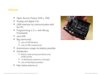
Arduino Microcontroller Boards • The power pins are as follows: • Vin. The input voltage to the Arduino board when it's using an external power source (as opposed to 5 volts from the USB connection or other regulated power source). You can supply voltage through this pin, or, if supplying voltage via the power jack, access it through this pin. • 5V. The regulated power supply used to power the microcontroller and other components on the board. This can come either from Vin via an on-board regulator, or be supplied by USB or another regulated 5V supply. • 3V3. A 3.3 volt supply generated by the on-board FTDI chip. Maximum current draw is 50 mA. • GND. Ground pins. USB connector Power connector 3V3 output 5V output Vin
Basics • In the Arduino environment programs are referred to as sketches • http://www.arduino.cc/ • http://arduino.cc/en/Reference/HomePage • http://arduino.cc/en/Tutorial/Foundations
breadboards • A breadboard is used to make up temporary circuits for testing or to try out an idea. • No soldering is required so it is easy to change connections and replace components. • Parts will not be damaged so they will be available to re-use afterwards. • http://www.kpsec.freeuk.com/breadb.htm
Basic Programming • void setup() • { • } • void loop() • { • }
int • Example • int ledPin = 13; • Syntax • int var = val;
/* * “Hello World!” * This is the Hello World! for Arduino. * It shows how to send data to the computer */ void setup() // run once, when the sketch starts { Serial.begin(9600); // set up Serial library at 9600 bps Serial.println("Is anybody out there?"); // prints phrase with ending line break } void loop() // run over and over again { // do nothing! } // After sending program to the Arduino, press Reset button on the board and watch Serial monitor
Basic Programming • The digitalWrite() functions outputs a value on a pin. • Possible values are: • LOW (0 V)or • HIGH (5 V) • For example: • digitalWrite(13, HIGH); • digitalWrite(11, LOW);
Basic Programming • The delay() causes the Arduino to wait for the specified number of milliseconds before continuing on to the next line. • There are 1000 milliseconds in a second, so the line: • delay(1000); • creates a delay of one second.
Find code examples here http://oomlout.com/a/products/ardx/
/* *Blink *Turns on an LED on for one second, then off for one second, repeatedly. *The circuit: * LED connected from digital pin 13 to ground. * Note: On most Arduino boards, there is already an LED on the board * connected to pin 13, so you don't need any extra components for this example. *Created 1 June 2005 *By David Cuartielles *http://arduino.cc/en/Tutorial/Blink *based on an orginal by H. Barragan for the Wiring i/o board*/int ledPin = 13; // LED connected to digital pin 13// The setup() method runs once, when the sketch startsvoid setup() { // initialize the digital pin as an output: pinMode(ledPin, OUTPUT); }// the loop() method runs over and over again,// as long as the Arduino has powervoid loop() { digitalWrite(ledPin, HIGH); // set the LED on delay(1000); // wait for a second digitalWrite(ledPin, LOW); // set the LED off delay(1000); // wait for a second}/* *Blink *Turns on an LED on for one second, then off for one second, repeatedly. *The circuit: * LED connected from digital pin 13 to ground. * Note: On most Arduino boards, there is already an LED on the board * connected to pin 13, so you don't need any extra components for this example. *Created 1 June 2005 *By David Cuartielles *http://arduino.cc/en/Tutorial/Blink *based on an orginal by H. Barragan for the Wiring i/o board*/int ledPin = 13; // LED connected to digital pin 13// The setup() method runs once, when the sketch startsvoid setup() { // initialize the digital pin as an output: pinMode(ledPin, OUTPUT); }// the loop() method runs over and over again,// as long as the Arduino has powervoid loop() { digitalWrite(ledPin, HIGH); // set the LED on delay(1000); // wait for a second digitalWrite(ledPin, LOW); // set the LED off delay(1000); // wait for a second}
int ledPin = 13; // LED connected to digital pin 13void setup() { pinMode(ledPin, OUTPUT); }void loop() { digitalWrite(ledPin, HIGH); // set the LED on delay(1000); // wait for a second digitalWrite(ledPin, LOW); // set the LED off delay(1000); // wait for a second}int ledPin = 13; // LED connected to digital pin 13void setup() { pinMode(ledPin, OUTPUT); }void loop() { digitalWrite(ledPin, HIGH); // set the LED on delay(1000); // wait for a second digitalWrite(ledPin, LOW); // set the LED off delay(1000); // wait for a second}
Making it Better? • Changing the pin: • The LED is connected to pin 13 but we can use any of the Arduino's pins. To change it take the wire plugged into pin 13 and move it to a pin of your choice (from 0-13) (you can also use analog 0-5 analog 0 is 14...) • Then in the code change the line: • int ledPin = 13; -> int ledPin = newpin; • Then upload the sketch: (ctrl-u)
Making it Better? • Change the Blink Time: • Unhappy with one second on one second off? • In the code change the lines: • digitalWrite(ledPin, HIGH); • delay(time on); //(seconds * 1000) • digitalWrite(ledPin, LOW); • delay(time off); //(seconds * 1000)
Making it Better? • Control the Brightness: • Along with digital (on/off) control the Arduino can control some pins in an analog (brightness) fashion. (more details on this in later circuits). To play around with it. • Change the LED to pin 9: (also change the wire) • ledPin = 13; -> int ledPin = 9; • Replace the code inside the { }'s of loop() with this: • analogWrite(ledPin, new number); • (new number) = any number between 0 and 255. 0 = off, 255 = on, in between = different brightness
Making it Better? • Fading: • We will use another included example program. To open go to. • File > Examples > Analog > Fading • Then upload to your board and watch as the LED fades in and then out.
What is this? IntledRed= 13; intledGreen = 11;intledYellow = 12; void setup(){pinMode(ledRed, OUTPUT); // sets the digital pin as outputpinMode(ledYellow, OUTPUT); // sets the digital pin as outputpinMode(ledGreen, OUTPUT); // sets the digital pin as output} void loop(){digitalWrite(ledGreen, HIGH); // sets the Green LED on delay(1000); // waits for a seconddigitalWrite(ledGreen, LOW); // sets the Green LED offdigitalWrite(ledYellow,HIGH); // sets the Yellow LED on delay(1000); // waits for a seconddigitalWrite(ledYellow, LOW); // sets the Yellow LED offdigitalWrite(ledRed, HIGH); // sets the Red LED on delay(1000); // waits for a seconddigitalWrite(ledRed, LOW); // sets the Reed LED off}
//LED Pin Variables int ledPins[] = {2,3,4,5,6,7,8,9}; //An array to hold the pin each LED is connected to //i.e. LED #0 is connected to pin 2, LED #1, 3 and so on //to address an array use ledPins[0] this would equal 2 //and ledPins[7] would equal 9/* * setup() - this function runs once when you turn your Arduino on * We the three control pins to outputs */
void setup(){ //Set each pin connected to an LED to output mode (pulling high (on) or low (off)for(int i = 0; i < 8; i++){ //this is a loop and will repeat eight timespinMode(ledPins[i],OUTPUT); //we use this to set each LED pin to output} //the code this replaces is below /* (commented code will not run) * these are the lines replaced by the for loop above they do exactly the * same thing the one above just uses less typing pinMode(ledPins[0],OUTPUT); pinMode(ledPins[1],OUTPUT); pinMode(ledPins[2],OUTPUT); pinMode(ledPins[3],OUTPUT); pinMode(ledPins[4],OUTPUT); pinMode(ledPins[5],OUTPUT); pinMode(ledPins[6],OUTPUT); pinMode(ledPins[7],OUTPUT); (end of commented code)*/}void setup(){ //Set each pin connected to an LED to output mode (pulling high (on) or low (off)for(int i = 0; i < 8; i++){ //this is a loop and will repeat eight timespinMode(ledPins[i],OUTPUT); //we use this to set each LED pin to output} //the code this replaces is below /* (commented code will not run) * these are the lines replaced by the for loop above they do exactly the * same thing the one above just uses less typing pinMode(ledPins[0],OUTPUT); pinMode(ledPins[1],OUTPUT); pinMode(ledPins[2],OUTPUT); pinMode(ledPins[3],OUTPUT); pinMode(ledPins[4],OUTPUT); pinMode(ledPins[5],OUTPUT); pinMode(ledPins[6],OUTPUT); pinMode(ledPins[7],OUTPUT); (end of commented code)*/}
/* * loop() - this function will start after setup finishes and then repeat * we call a function called oneAfterAnother(). if you would like a different behaviour * uncomment (delete the two slashes) one of the other lines */void loop() // run over and over again{ oneAfterAnotherNoLoop(); //this will turn on each LED one by one then turn each off //oneAfterAnotherLoop(); //does the same as oneAfterAnotherNoLoop but with //much less typing //oneOnAtATime(); //this will turn one LED on then turn the next one //on turning the //former off (one LED will look like it is scrolling //along the line //inAndOut(); //lights the two middle LEDs then moves them out then back //in again/* * loop() - this function will start after setup finishes and then repeat * we call a function called oneAfterAnother(). if you would like a different behaviour * uncomment (delete the two slashes) one of the other lines */void loop() // run over and over again{ oneAfterAnotherNoLoop(); //this will turn on each LED one by one then turn each off //oneAfterAnotherLoop(); //does the same as oneAfterAnotherNoLoop but with //much less typing //oneOnAtATime(); //this will turn one LED on then turn the next one //on turning the //former off (one LED will look like it is scrolling //along the line //inAndOut(); //lights the two middle LEDs then moves them out then back //in again
void oneAfterAnotherNoLoop(){int delayTime = 100; //the time (in milliseconds) to pause between LEDs //make smaller for quicker switching and larger for slower digitalWrite(ledPins[0], HIGH); //Turns on LED #0 (connected to pin 2 ) delay(delayTime); //waits delayTime milliseconds digitalWrite(ledPins[1], HIGH); //Turns on LED #1 (connected to pin 3 ) delay(delayTime); //waits delayTime milliseconds digitalWrite(ledPins[2], HIGH); //Turns on LED #2 (connected to pin 4 ) delay(delayTime); //waits delayTime milliseconds digitalWrite(ledPins[3], HIGH); //Turns on LED #3 (connected to pin 5 ) delay(delayTime); //waits delayTime milliseconds digitalWrite(ledPins[4], HIGH); //Turns on LED #4 (connected to pin 6 ) delay(delayTime); //waits delayTime milliseconds digitalWrite(ledPins[5], HIGH); //Turns on LED #5 (connected to pin 7 ) delay(delayTime); //waits delayTime milliseconds digitalWrite(ledPins[6], HIGH); //Turns on LED #6 (connected to pin 8 ) delay(delayTime); //waits delayTime milliseconds digitalWrite(ledPins[7], HIGH); //Turns on LED #7 (connected to pin 9 ) delay(delayTime); //waits delayTime milliseconds void oneAfterAnotherNoLoop(){int delayTime = 100; //the time (in milliseconds) to pause between LEDs //make smaller for quicker switching and larger for slower digitalWrite(ledPins[0], HIGH); //Turns on LED #0 (connected to pin 2 ) delay(delayTime); //waits delayTime milliseconds digitalWrite(ledPins[1], HIGH); //Turns on LED #1 (connected to pin 3 ) delay(delayTime); //waits delayTime milliseconds digitalWrite(ledPins[2], HIGH); //Turns on LED #2 (connected to pin 4 ) delay(delayTime); //waits delayTime milliseconds digitalWrite(ledPins[3], HIGH); //Turns on LED #3 (connected to pin 5 ) delay(delayTime); //waits delayTime milliseconds digitalWrite(ledPins[4], HIGH); //Turns on LED #4 (connected to pin 6 ) delay(delayTime); //waits delayTime milliseconds digitalWrite(ledPins[5], HIGH); //Turns on LED #5 (connected to pin 7 ) delay(delayTime); //waits delayTime milliseconds digitalWrite(ledPins[6], HIGH); //Turns on LED #6 (connected to pin 8 ) delay(delayTime); //waits delayTime milliseconds digitalWrite(ledPins[7], HIGH); //Turns on LED #7 (connected to pin 9 ) delay(delayTime); //waits delayTime milliseconds
//Turns Each LED Off digitalWrite(ledPins[7], LOW); //Turns on LED #0 (connected to pin 2 ) delay(delayTime); //waits delayTime milliseconds digitalWrite(ledPins[6], LOW); //Turns on LED #1 (connected to pin 3 ) delay(delayTime); //waits delayTime milliseconds digitalWrite(ledPins[5], LOW); //Turns on LED #2 (connected to pin 4 ) delay(delayTime); //waits delayTime milliseconds digitalWrite(ledPins[4], LOW); //Turns on LED #3 (connected to pin 5 ) delay(delayTime); //waits delayTime milliseconds digitalWrite(ledPins[3], LOW); //Turns on LED #4 (connected to pin 6 ) delay(delayTime); //waits delayTime milliseconds digitalWrite(ledPins[2], LOW); //Turns on LED #5 (connected to pin 7 ) delay(delayTime); //waits delayTime milliseconds digitalWrite(ledPins[1], LOW); //Turns on LED #6 (connected to pin 8 ) delay(delayTime); //waits delayTime milliseconds digitalWrite(ledPins[0], LOW); //Turns on LED #7 (connected to pin 9 ) delay(delayTime); //waits delayTime milliseconds }//Turns Each LED Off digitalWrite(ledPins[7], LOW); //Turns on LED #0 (connected to pin 2 ) delay(delayTime); //waits delayTime milliseconds digitalWrite(ledPins[6], LOW); //Turns on LED #1 (connected to pin 3 ) delay(delayTime); //waits delayTime milliseconds digitalWrite(ledPins[5], LOW); //Turns on LED #2 (connected to pin 4 ) delay(delayTime); //waits delayTime milliseconds digitalWrite(ledPins[4], LOW); //Turns on LED #3 (connected to pin 5 ) delay(delayTime); //waits delayTime milliseconds digitalWrite(ledPins[3], LOW); //Turns on LED #4 (connected to pin 6 ) delay(delayTime); //waits delayTime milliseconds digitalWrite(ledPins[2], LOW); //Turns on LED #5 (connected to pin 7 ) delay(delayTime); //waits delayTime milliseconds digitalWrite(ledPins[1], LOW); //Turns on LED #6 (connected to pin 8 ) delay(delayTime); //waits delayTime milliseconds digitalWrite(ledPins[0], LOW); //Turns on LED #7 (connected to pin 9 ) delay(delayTime); //waits delayTime milliseconds }
void oneAfterAnotherLoop(){ int delayTime = 100; //the time (in milliseconds) to pause between LEDs //make smaller for quicker switching and larger for slower//Turn Each LED on one after another for(int i = 0; i <= 7; i++){digitalWrite(ledPins[i], HIGH); //Turns on LED #i each time this runs i delay(delayTime); //gets one added to it so this will repeat } //8 times the first time i will = 0 the final //time i will equal 7;//Turn Each LED off one after another for(int i = 7; i >= 0; i--){ //same as above but rather than starting at 0 and counting up //we start at seven and count down digitalWrite(ledPins[i], LOW); //Turns off LED #i each time this runs idelay(delayTime); //gets one subtracted from it so this will repeat } //8 times the first time i will = 7 the final //time it will equal 0 }void oneAfterAnotherLoop(){ int delayTime = 100; //the time (in milliseconds) to pause between LEDs //make smaller for quicker switching and larger for slower//Turn Each LED on one after another for(int i = 0; i <= 7; i++){digitalWrite(ledPins[i], HIGH); //Turns on LED #i each time this runs i delay(delayTime); //gets one added to it so this will repeat } //8 times the first time i will = 0 the final //time i will equal 7;//Turn Each LED off one after another for(int i = 7; i >= 0; i--){ //same as above but rather than starting at 0 and counting up //we start at seven and count down digitalWrite(ledPins[i], LOW); //Turns off LED #i each time this runs idelay(delayTime); //gets one subtracted from it so this will repeat } //8 times the first time i will = 7 the final //time it will equal 0 }
Your Turn • Try and explain the functions bellow. //oneOnAtATime(); //inAndOut();
Function Call • Program will jump to ”motorOnThenOff()” • Code inside {} of motorOnThenOff() will be executed • Program will comback one instruction bellow motorOnThenOff(); void loop() // run over and over again{motorOnThenOff(); //motorOnThenOffWithSpeed(); //motorAcceleration();}
void motorOnThenOff(){ int onTime = 2500; //the number of milliseconds for the motor to turn on for int offTime = 1000; //the number of milliseconds for the motor to turn off for digitalWrite(motorPin, HIGH); // turns the motor On delay(onTime); // waits for onTime milliseconds digitalWrite(motorPin, LOW); // turns the motor Off delay(offTime); // waits for offTime milliseconds}void motorOnThenOff(){ int onTime = 2500; //the number of milliseconds for the motor to turn on for int offTime = 1000; //the number of milliseconds for the motor to turn off for digitalWrite(motorPin, HIGH); // turns the motor On delay(onTime); // waits for onTime milliseconds digitalWrite(motorPin, LOW); // turns the motor Off delay(offTime); // waits for offTime milliseconds}
motorOnThenOffWithSpeed() /* * motorOnThenOffWithSpeed() - turns motor on then off but uses speed values as well * (notice this code is identical to the code we used for * the blinking LED) */void motorOnThenOffWithSpeed(){ int onSpeed = 200; // a number between 0 (stopped) and 255 (full speed) int onTime = 2500; //the number of milliseconds for the motor to turn on for int offSpeed = 50; // a number between 0 (stopped) and 255 (full speed) int offTime = 1000; //the number of milliseconds for the motor to turn off for analogWrite(motorPin, onSpeed); // turns the motor On delay(onTime); // waits for onTime milliseconds analogWrite(motorPin, offSpeed); // turns the motor Off delay(offTime); // waits for offTime milliseconds}
motorAcceleration() /* * motorAcceleration() - accelerates the motor to full speed then * back down to zero*/void motorAcceleration(){ int delayTime = 50; //milliseconds between each speed step //Accelerates the motorfor(int i = 0; i < 256; i++){ //goes through each speed from 0 to 255analogWrite(motorPin, i); //sets the new speed delay(delayTime); // waits for delayTime milliseconds} //Decelerates the motor for(int i = 255; i >= 0; i--){ //goes through each speed from 255 to 0analogWrite(motorPin, i); //sets the new speeddelay(delayTime); // waits for delayTime milliseconds}}
ARDX • Practice examples: • 1, 2, 3, 6, 7, 8
Button • Pushbuttons or switches connect two points in a circuit when you press them. This example turns on the built-in LED on pin 13 when you press the button.
int buttonPin = 2; // the number of the pushbutton pin int ledPin = 13; // the number of the LED pin int buttonState = 0; // variable for reading the pushbutton status void setup() { pinMode(ledPin, OUTPUT); // initialize the LED pin as an output: pinMode(buttonPin, INPUT); // initialize the pushbutton pin as an input: } void loop(){ buttonState = digitalRead(buttonPin); // read the state of the pushbutton value: if (buttonState == HIGH) { // check if the pushbutton is pressed. If it is, the buttonState is HIGH: digitalWrite(ledPin, HIGH); // turn LED on: } else { digitalWrite(ledPin, LOW); // turn LED off: } }
Button • The problem with the last program is that the switch has to remain pressed in order for the LED to turn on • We want the LED to change state when we press the button and to stay in the new state when the button is released
int buttonPin = 2; // the pin that the pushbutton is attached to int ledPin = 13; // the pin that the LED is attached to int buttonState = 0; // current state of the button int lastLEDState = 0; // previous state of the button void setup() { pinMode(buttonPin, INPUT); // initialize the button pin as a input: pinMode(ledPin, OUTPUT); // initialize the LED as an output: } void loop() { buttonState = digitalRead(buttonPin); // read the pushbutton input pin: if (buttonState == HIGH) { // Determine if button State is HIGH if (lastLEDState == HIGH) { // if the current state is HIGH then turn LED off digitalWrite(ledPin, LOW); lastLEDState = LOW; } else {// if the current state is LOW then turn LED on digitalWrite(ledPin, HIGH); lastLEDState = HIGH; } while(buttonState == HIGH){ buttonState = digitalRead(buttonPin); // read the pushbutton input pin: }; delay(250); } }