Download
1 / 2
20 likes | 57 Views
This pressure regulator provides the highest level of regulation accuracy and repeatability available in a compact, lightweight housing. A force balanced pilot control maintains output pressure to within 0.05 psig (3.44 millibar) with minimal drift over time. The Type 90 is ideal for applications that require exact pressure control and substantial flow capacity under variable operating conditions and limited space.<br><br>For More Information visit on:- www.seeautomation.com<br>Our Mail I.D:- sales@seeautomation.com<br>Contact Us:- 91-11-22012324<br>

E N D
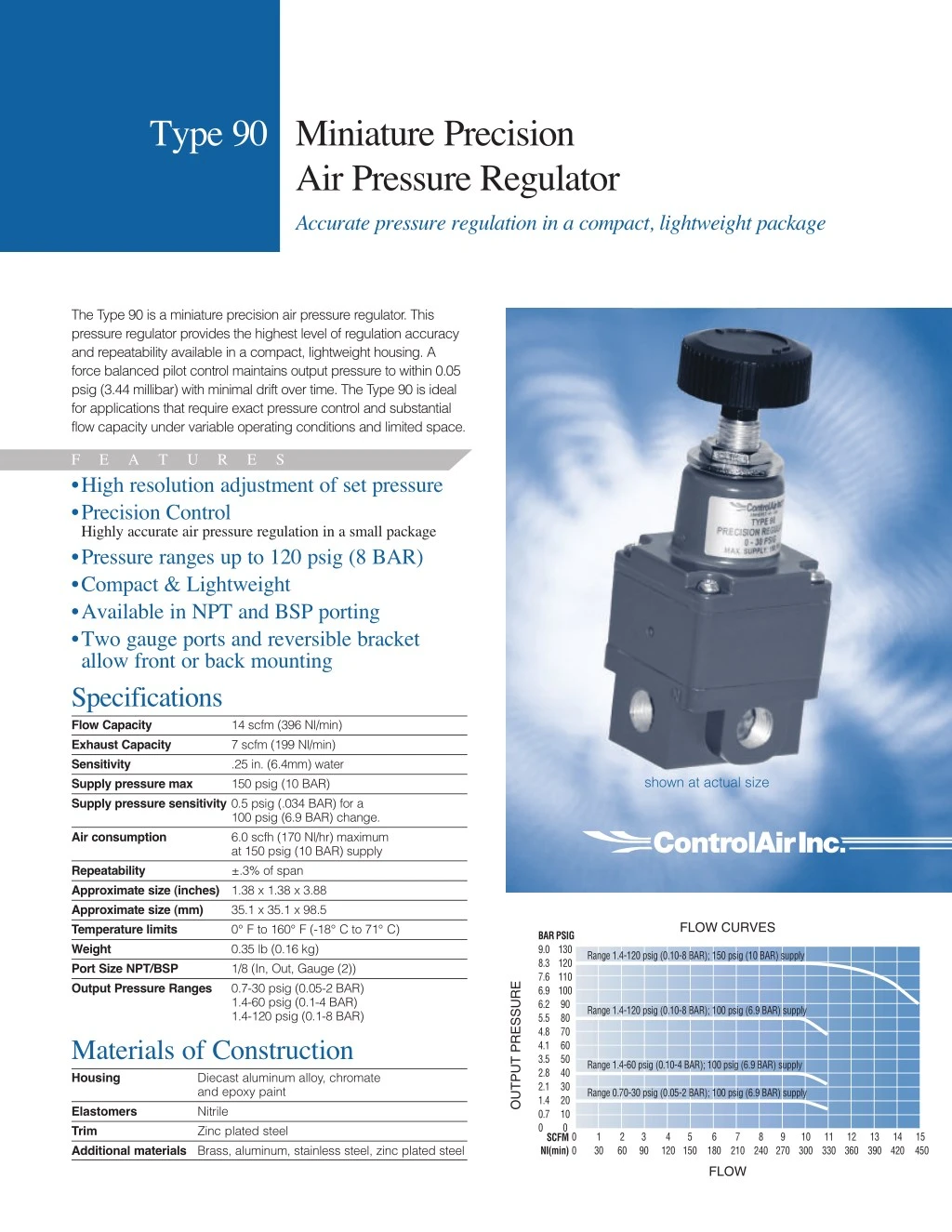
Type 90 Miniature Precision Air Pressure Regulator Accurate pressure regulation in a compact, lightweight package The Type 90 is a miniature precision air pressure regulator. This pressure regulator provides the highest level of regulation accuracy and repeatability available in a compact, lightweight housing. A force balanced pilot control maintains output pressure to within 0.05 psig (3.44 millibar) with minimal drift over time. The Type 90 is ideal for applications that require exact pressure control and substantial flow capacity under variable operating conditions and limited space. F •High resolution adjustment of set pressure •Precision Control Highly accurate air pressure regulation in a small package •Pressure ranges up to 120 psig (8 BAR) •Compact & Lightweight •Available in NPT and BSP porting •Two gauge ports and reversible bracket allow front or back mounting Specifications Flow Capacity 14 scfm (396 Nl/min) Exhaust Capacity 7 scfm (199 Nl/min) Sensitivity .25 in. (6.4mm) water Supply pressure max 150 psig (10 BAR) Supply pressure sensitivity 0.5 psig (.034 BAR) for a 100 psig (6.9 BAR) change. Air consumption 6.0 scfh (170 Nl/hr) maximum at 150 psig (10 BAR) supply Repeatability ±.3% of span Approximate size (inches) 1.38 x 1.38 x 3.88 Approximate size (mm) 35.1 x 35.1 x 98.5 Temperature limits 0° F to 160° F (-18° C to 71° C) Weight 0.35 lb (0.16 kg) Port Size NPT/BSP 1/8 (In, Out, Gauge (2)) Output Pressure Ranges 0.7-30 psig (0.05-2 BAR) 1.4-60 psig (0.1-4 BAR) 1.4-120 psig (0.1-8 BAR) Materials of Construction Housing Diecast aluminum alloy, chromate and epoxy paint Elastomers Nitrile Trim Zinc plated steel Additional materials Brass, aluminum, stainless steel, zinc plated steel E A T U R E S shown at actual size FLOW CURVES BAR PSIG 9.0 130 8.3 120 7.6 110 6.9 100 6.2 90 5.5 80 4.8 70 4.1 60 3.5 50 2.8 40 2.1 30 1.4 20 0.7 10 0 SCFM NI(min) Range 1.4-120 psig (0.10-8 BAR); 150 psig (10 BAR) supply OUTPUT PRESSURE Range 1.4-120 psig (0.10-8 BAR); 100 psig (6.9 BAR) supply Range 1.4-60 psig (0.10-4 BAR); 100 psig (6.9 BAR) supply Range 0.70-30 psig (0.05-2 BAR); 100 psig (6.9 BAR) supply 0 0 0 1 30 2 60 3 90 4 5 6 7 8 9 10 11 12 13 14 15 120 150 180 210 240 270 300 330 360 390 420 450 FLOW
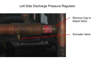
Type 90 Dimensions 1.14 [29.1] IN [mm] OPTIONAL BRACKET 1.20 [30.5] 1.63 [41.5] (Approx.) 3/8 - 24 UNF 5/32 MAX. 3.63 [92.2] AT MAX. OUTPUT (Approx.) R.17 [R4.3] PANEL HOLE 0.39 [9.91] VENT BLEED 2.53 [64.2] 2.17 [55.1] 1.72 [43.6] .70 [17.8] 1.64 [41.6] OUT IN .40 [10.1] (2) GAUGE PORTS .85 [21.6] EXHAUST 2.00 1.37 [34.9] OPTIONAL GAUGE (Approx.) 1.37 [34.9] Manifold Mount 1.10 [27.9] Type 90 Ordering Information 1.98 [50.2] Use this coding system to order INPORT .46 [11.6] Ø.18 [Ø4.5] THRU (2) PLACES 90 .52 [13.3] 1.42 [36.1] Model • • Port Range A- .70-30 psig (0.05-2.0 BAR) B- 1.40-60 psig (0.10-4.0 BAR) C- 1.40-120 psig (0.10-8.0 BAR) 4.29 [108.9] A - 1/8 NPT U - 1/8 BSP X - Manifold .63 [15.9] OUTPORT 1.72 [43.6] .84 [21.3] Accessories Mounting Bracket: Pressure Gauge (1.5” dual scale face): Range 0-30.0 psig (0-2 BAR) 0-60.0 psig (0-4 BAR) 0-160.0 psig (0-8 BAR) P/N: 436-707-075 OUT .47 [12.1] IN Theory of Operation NPT P/N: 446-725-006 P/N: 446-725-007 P/N: 446-725-008 BSP P/N: 446-725-030 P/N: 446-725-031 P/N: 446-725-032 Supply air is introduced to the inlet port, air flows through the supply side orifice and on top of the control diaphragm. That air then flows up through the housing nozzle and escapes out the housing vent. When the knob is adjusted to a setpoint, the range spring exerts a downward force against the signal diaphragm assembly. This force is transmitted to the flapper (ball), restricting airflow through the housing nozzle and creating backpressure against the control diaphragm. The backpressure will build until enough downward force to open the supply valve is achieved. Output pressure is then routed to the underside of the pilot diaphragm creating an upward force and also against the signal diaphragm, creating a downward force. These forces against the signal and pilot diaphragm will allow the flapper to move upward, venting the pressure above the control diaphragm. Venting will continue until the upward forces against the signal diaphragm and control diaphragm are in balance with the downward forces against the pilot diaphragm and control diaphragm. Warranty ControlAir, Inc. products are warranted to be free from defects in materials and workmanship for a period of eighteen months from the date of sale, provided said products are used according to ControlAir, Inc. recommended usages. ControlAir, Inc.'s liability is limited to the repair, purchase price refund, or replacement in kind, at ControlAir, Inc.'s sole option, of any products proved defective. ControlAir, Inc. reserves the right to discontinue manufacture of any products or change products materials, designs or specifications without notice. Note: ControlAir does not assume responsibility for the selection, use, or maintenance of any product. Responsibility for the proper selection, use, and maintenance of any ControlAir product remains solely with the purchaser and end user. Supply Output Exhaust Atmosphere When the range spring force is reduced, the flapper lifts off the nozzle and vents the pressure above the control diaphragm. The control diaphragm will lift up off the supply valve allowing the valve to close and the output pressure to vent through the valve stem. 8 Columbia Drive / Amherst, NH 03031 USA Website: www.controlair.com Email: sales@controlair.com 603-886-9400 FAX 603-889-1844 P/N 441-625-061 03/22/11