Download
1 / 32
320 likes | 592 Views
Gamma-ray Large Area Space Telescope. PDU TRR. GLAST Large Area Telescope: Presented by P. Young SLAC plsyoung@slac.stanford.edu (650) 926-4257. Contents. Introduction Overview Significant Changes since CDR Objectives Status Requirements/Verification EGSE and Test-Procedures

E N D
Gamma-ray Large Area Space Telescope PDU TRR GLAST Large Area Telescope: Presented by P. Young SLAC plsyoung@slac.stanford.edu (650) 926-4257
Contents • Introduction • Overview • Significant Changes since CDR • Objectives • Status • Requirements/Verification • EGSE and Test-Procedures • Verification Test Plan and Flow • At Assembly Vendor • Test-plan and Flow • Facility • Man-Power • Quality Assurance • Vibration • At SLAC • Test-plan and Flow • Thermal Vacuum Test • Mass Property • EMI/EMC (at sub-contractor) • Man-Power • Quality Assurance • Equipment Calibration/Safety • Risk Assessment • Schedule • Status of Procedures • Issues and Concerns
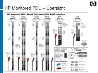
LAT Electronics TKR Front-End Electronics (MCM) ACD Front-End Electronics (FREE) TKR CAL Front-End Electronics (AFEE) 16 Tower Electronics Modules & Tower Power Supplies CAL Global-Trigger/ACD-EM/Signal-Distribution Unit* 3 Event-Processor Units (EPU) (2 + 1 spare) • Event processing CPU • LAT Communication Board • SIB Spacecraft Interface Units (SIU)* • Storage Interface Board (SIB): Spacecraft interface, control & telemetry • LAT control CPU • LAT Communication Board (LCB): LAT command and data interface Power-Distribution Unit (PDU)* • Spacecraft interface, power • LAT power distribution • LAT health monitoring * Primary & Secondary Units shown in one chassis
EGSE PDU Mounted on LAT GASU PDU
Flight PDU Primary and Redundant PDU DAQ Module in same enclosure, separated by metal
Power Distribution Module • One enclosure houses primary and redundant Power Distribution DAQ Circuit Card Assembly • Separated by aluminum wall • Receives primary and redundant 28V DAQ feed from spacecraft • Common mode filter • Selects whether to use primary or redundant feed for a selected DAQ board via control signals from SIU • Receives LAT command link from primary and redundant SIU into on-board ACTEL FPGA (via LVDS converter IO) • On/off control of power to each of the loads: 16 TEM/TPS, 3 EPU’s, via configuration registers • Readback of configuration registers to SIU • Includes under-voltage, over-current protection and inrush current limiting for each output feed • Digitization of 28 primary and 28 redundant RTD and 97 primary and 97 redundant thermistor sensor values • Block redundancy: all primary sensors are connected to primary PDU, all redundant sensors are connected to redundant PDU • Digitization in response to “digitize” command • Readback of results after fixed minimum latency • PDU 3.3V-supply voltage level and thermistor interface to spacecraft
Changes since LAT CDR • Modification of FPGA code • Code was rewritten by Eric Siskind • Code was reviewed by GSFC reviewer (Dr Rod) • Some resistor/capacitor values have changed to optimize monitoring ranges • Details of monitoring circuit have changed • Redesigned load-switch circuit • To incorporate under-voltage protection • Added in case space-craft converters enters current-limiting mode with subsequent drop in output voltage • To incorporate over-current protection • Avoids damage to MOSFET switches • Changed resistor values to optimize in-rush current level • Worst Case Analysis updated to incorporate changes • Thermal Analysis from CDR/Delta-CDR remained since changes don’t impact thermal performance
Objectives • Demonstrate that hardware, software, procedures, and support equipment are prepared to support system environmental test • Demonstrate that planned and completed testing meets performance and interface requirements • Identify and understand all the risks and limitations • TRR is not intended to • Review PDU design • Review flight readiness • Buy-off hardware or software • RFA’s should only be of sufficient concern to stop test • Prior to start of an given test, any applicable TRR RFAs must be closed
Test Entrance / Exit Criteria • Entrance • All required paperwork released and in place • Procedures, drawings, etc • Test configuration verified and approved • Essential personnel in place • Pre-test PDU functional successfully passed • Exit • As-run procedures completed • Correct and accurate application of test environment • Test data acquired and archived • No damage to PDU • PDU performance within specification limits • Post-test PDU functional successful
Status • First PDU (to be proto-flight tested) • Assembled • Pre-conformal coat PDU with enclosure-internal EGSE harness tested, tests to verify that ACTEL performs over temperature performed (was prerequisite to programming FPGA’s for second PDU box) • Conformal coated, integrated in enclosure with flight harness • Final PDU to be delivered to SLAC week of July 18, 2005 • Second PDU (to be flight acceptance tested) • Will be spare or primary flight PDU, depending on schedule • Board went thru reflow surface-mount assembly step • ACTEL FPGA’s were programmed and are being assembled on boards • Remaining are staking, integration of boards into enclosure, integration of EGSE harness, testing at SLAC, conformal coating, integration of flight harness, testing
Tests To-Date • PDU engineering modules were extensively tested • As EGSE in DAQ/I&T • Testbed includes PDU for > 1 year • I&T uses EGSE PDU during integration of towers in LAT for several months • Main difference to flight PDU: under-voltage/over-current circuit was not implemented on EGSE PDU’s supplied to I&T and testbed • One flight board was assembled with mostly flight parts and tested • Additional PDU tests • Informal thermal test -40C to 55C • Informal EMI test on EGSE station sent to Lockheed for thermal test
Requirements • LAT-SS-00285 Specifications, Level 4 LAT Dataflow System • LAT-SS-00019 Specifications, Level 3 T&DF Subsystem Specification • LAT-SS-00136 Specifications, Level 3 Power Supply System • LAT-SS-00183 Specifications, Level 4 Power Supply System • LAT-SS-06988 Specifications, Level 5 PDU Specification • LAT-TD-00606 LAT Inter-Module Communications • LAT-TD-01743 PDU ICD Specification & Conceptual Design • LAT-TD-01543 PDU, Programming ICD • LAT-SS-00778 LAT Environmental Specification • LAT-SS-06988 PDU lists requirements • LAT-TD-06989 contains Verification Matrix which gives approach to verify each requirement • Lists verification method used
System Performance • Level 3 and level 4 DAQ and TRG and power-system requirements are met with a combination of DAQ modules (TEM/TPS, GASU, SIU, PDU, etc), since the DAQ and trigger and power system is comprised of several sub-system module types • Level 5 PDU requirements which are verified are derived from Level 3 and Level 4 DAQ and Trigger and Power system specifications (as noted in the L5 requirements doc) • Level 5 requirement doc includes derived requirement addressing • Functionality/performance • Power • Mass/C.G. • EMI/EMC • Environmental incl temperature and vibration
Verification Status • Engineering Module PDU • EM completed full functional test program with exception of thermal-vacuum, EMI/EMC, mass, and C.G. • Demonstrated compliance with specifications
EGSE and Test-Procedures • EGSE for Functional/Performance Tests • Test-Stand documented in LAT-DS-06627 • Test-Procedures • LAT-TD-04332 Electrical Interface Continuity and Isolation Test procedure • Power-off impedance tests of I/O • LAT-TD-04384 Stray-Voltage-Test Procedure • Power-on voltage test of I/O • LAT-TD-01744 Comprehensive Test Procedure • Functionality and Performance test
EGSE Test-Configuration • LAT-TD-01744-03
Verification Level – Module Detail • Breakout of verification at PDU Module Level • Tests to be conducted after successful TRR (order may change depending on availability of resourced (TV/EMI) • EICIT & SVT • Functional test • Vibration (Wyle) • Functional test • Thermal cycle • Functional test • Mass properties including CG • Thermal vacuum (in-situ testing) • EMI/EMC (at CKC-lab for proto-flight, at SLAC for flight acceptance) • Functional test • Review • Deliver to I&T • DAQ (out-going) / I&T (incoming) test combined
Verification • Test-Stand • Supplied by SLAC • Operated by SLAC engineers • Vibration facility at Wyle • LAT-TD-06101 Vibration test-procedure • SLAC engineers present for vibration tests • Thermal Cycle in thermal chamber in SLAC clean-room
TC and Vibration Requirements Figure 1. Vibration Levels, Duration, and Spectra
Mass Property • Mass properties checked at SLAC • Procedure to be written (performed at SLAC Metrology) • Expected: (ref LAT-TD-00564) • Total 9.8 kg • Allocation 12% above = 11 kg • C.G. to be measured for the proto-flight unit only
Thermal Vacuum Test • Thermal Vacuum facility in Building 33 at SLAC • Thermal Vacuum Chamber Operating Procedure LAT-TD-02541 • PDU Thermal Vacuum Test-Procedure LAT-TD-03639 • First PDU tested to proto-flight specifications (same Temperatures as qualification, but 4 TV cycles versus 12 cycles)
Proto-Flight and Flight Acceptance Thermal Vacuum Test • See PDU Thermal Vacuum Test-Procedure LAT-TD-03639 At < 10-5 Torr X 4
EMI/EMC Test • Proto-Flight = Qualification Test (Conductive & Radiative) • Sub-contracted to CK Labs • Statement of Work: LAT-PS- 04568 • CE102, CECN, CS102, CSCM, CS06, RE101, RE102, RS101, RS103 • Detailed EMI/EMC procedure provided by CKC lab (TP05-83489-0.doc, to be released?) • SLAC engineers present at vendor for tests • Vendor supplies test-report • LAT QA at SLAC present for tests • Flight Acceptance Test (Conductive) • Performed at SLAC • LAT-TD-03637 • Only CE102, CS102 • SLAC supplies test-report • LAT QA at SLAC present for tests
Manpower & Quality Assurance • Test man-power • PDU: Patrick Young • Test Support: J. Ludvik • Thermal Cycle and TV support: R. Williams, P. Hart • TV shift support: 2 contractors • EMI support: D. Nelson • Vibration support: D. Tarkington • Quality assurance: Joe Cullinan • QA representative (Y.C. Liew) present during tests, review of test-procedure and results • Required changes to documentation are red-lined and included in new revisions • NCR are created for non-conformance (e.g. exceeding of min/max test limits) and submitted for disposition
Problem Failure Report/ Configuration Management • Problem Failure Reporting • Via standard SLAC LAT Non-Conformance Reporting (NCR) System • NCR is entered • Reviewed/accepted/resolved • LAT engineering • LAT QC • Already exercised during pre-conformal coat PDU assembly • Configuration Management • Via standard LATDOC system
Planned Tests • Function/Performance Tests (LAT-TD-01744) • Verifies all requirements in LAT-SS-06988 except below • Thermal Vacuum Tests • Verifies performance/function over temperature • Mass/C.G. • Verifies/measures mass and C.G. • Vibrations test • Verifies vibration performance requirements • EMI/EMC • Verifies EMI/EMC performance • Note to margin testing • External Voltage margin testing is performed at all stages (28V +/-1V) • Internal Voltage margin testing (3.3V/2.5V) is only performed at pre-conformal coat stage while using internal EGSE harness • No internal voltage margin testing once flight harness is used. Respective tests in TD-01744 are omitted at that stage as will be documented in work-order • Frequency margin tested pre-conformal coat as well as on final PDU • Temperature testing performed during TV testing
Equipment Calibration • Electrical Functional Test Equipment • EGSE Test-Stand documented at • http://www-glast.slac.stanford.edu/Elec_DAQ/EGSE/I&TPDU/TESTSTAND_1164/teststand1164docs.htm • EMI/EMC Test Equipment • Quantitative measurement equipment (sensors, antennas, etc) calibrated to NIST standards • Calibration performed annually • All item are (will be) within calibration at time of testing • Vibration Test Equipment • Accelerometers calibrated against a standard accelerometer traceable to NIST • Signal conditioners calibrated annually • TVAC Equipment • Thermocouples calibrated against standard temperature; calibrated prior to test • Thermocouple reader calibrated very 2 years
Sub-System Safety • EGSE • Safe-to-mate • Configuration control • Calibration verification • Functionality verification with “golden” EGSE PDU prior to test with flight hardware • MGSE • No custom MGSE • Environment • Temperature controlled in all test-facilities • Cleanliness actively controlled in clean-room; hardware bagged and purged when required • Training • ESD training completed • Clean room training completed
Risk Assessment • Schedule • Pressure to deliver flight hardware could force less than complete characterization and analysis of modules, could result in replicating a problem in the second module • Performance • None known • Software to support TV test is still in development
Test-Schedule • Estimated as follows, order subject to EMI/TV availability • First PDU • 7/25: functional test • 7/28: vibration test • 7/29: functional test • 8/1: TC • 8/2: functional test • 8/3: EMI start • 8/17: EMI end • 8/18: mass, c.g. property • 8/9: TV start • 8/29: TV end • 2nd PDU • Lags first PDU by about 8 weeks
Status of Main Test Procedures • All procedures must be released before respective test • Procedures to be released • Mass/CG procedure to be written/released • EMI vendor procedure to be released • CPT and TV modified, revisions are in review • Vibration procedure released?
Issue & Concerns • Schedule • Tight • Vibration test • Concern that harness/connectors pass vibration tests • (should be ok, but is concern)