Download
1 / 67
730 likes | 1.04k Views
Recent Topics of Welding Metallurgy Relating to Hot Cracking and Embrittlement in Iron and Nickel-base Alloys. Osaka University. Kazutoshi Nishimoto Department of Manufacturing Science Graduate School of Engineering Osaka University. Lab. Material Joining Process. Contents.

E N D
Recent Topics of Welding Metallurgy Relating to Hot Cracking and Embrittlement in Iron and Nickel-base Alloys Osaka University Kazutoshi Nishimoto Department of Manufacturing Science Graduate School of Engineering Osaka University Lab. Material Joining Process
Contents Osaka University 1. Background 2. Prediction of Degree of Embrittlement ■475 ℃Embrittlement ■Sigma Phase Embrittlement 3. Mechanism of Weld Cracking ■Solidification Cracking in Laser Welding ■Ductility-dip Cracking 4. Summary Lab. Material Joining Process
Contents Osaka University 1. Background 2. Prediction of Degree of Embrittlement ■475 ℃Embrittlement ■Sigma Phase Embrittlement 3. Mechanism of Weld Cracking ■Solidification Cracking in Laser Welding ■Ductility-dip Cracking 4. Summary Lab. Material Joining Process
Prevalent problems in welds of iron-base and nickel-base alloys Osaka University The use of new alloys or new welding processes σphase embrittlement δferrite content Hot cracking Need for researches to understand their response to these problems. Nieq=%Ni+30×%C+0.5×%Mn Embrittlement by grain coarsened ・475℃ embrittlement Cold cracking Creq=%Cr+%Mo+0.5×%Si+0.5×%Nb ■New welding processes such as laser welding may cause changes in a susceptibility to weld cracking that requires further investigation. ■ Invar alloy which has recently become widely used in cryogenic plants, is found sensitive to hot cracking, but its mechanism is not clarified yet.⇒ Lab. Material Joining Process
Prevalent problems in welds of iron-base and nickel-base alloys Osaka University The use of new alloys or new welding processes σphase embrittlement δferrite content Hot cracking Nieq=%Ni+30×%C+0.5×%Mn Need for researches to understand their response to these problems. Embrittlement by grain coarsened ・475℃ embrittlement Cold cracking Creq=%Cr+%Mo+0.5×%Si+0.5×%Nb ■Embrittlement is also a serious problem in weldments of especially ferritic or duplex stainless steels. ■Although many investigations have been conducted into the material behavior producing embrittlement, rather few of these are useful for predicting the degree of embrittlement of the alloys during welding and/or in post-heat treatment. ⇒
Contents Osaka University 1. Background 2. Prediction of Degree of Embrittlement ■475 ℃Embrittlement ■Sigma Phase Embrittlement 3. Mechanism of Weld Cracking ■Solidification Cracking in Laser Welding ■Ductility-dip Cracking 4. Summary Lab. Material Joining Process
Spinodal Phase Decomposition in Chromium Containing Iron base Alloys Osaka University Nucleation and growth Cα’’ (a) C 0 Cα’ G C Spinodal decomposition Cα’’ C 0 Cα’ Initial Middle Final ■ When ferritic or duplex stainless steels containing more than about 20 % Cr are exposed to temperatures of 673-823K, they may suffer from "475 ℃ embrittlement", which somewhat limits the operating temperatures of their applications. Spinodal decomposition (b) α α’+α’’ G Cα’’ 0 1 Cα Cα’ (a) Free energy curve (b) Phase diagram and Spinodal curve Lab. Material Joining Process
Theoretical Analysis of Spinodal Decomposition during iso-thermal Process Osaka University Cahn-Hilliard's non-linear diffusion equation ■The Cahn-Hilliard non-linear diffusion equation is one of the most useful approaches to spinodal phase decomposition. ■Recently, Miyazaki proposed a general formula with a Fourier expression of this non-linear diffusion equation. However, these approaches are meant to be used, for isothermal heat-treatment, and cannot be directly applied these to a phenomenon during the welding process. Fourier expression of diffusion equation Lab. Material Joining Process
The Method of Analysis for Spinodal Decomposition in thermal cycle process Osaka University Cahn-Hilliard's non-linear diffusion equation (extended) Interdiffusion coefficient Gradient energy coefficient ■Developed the method of analysis for the decomposition in thermal cycle process by extending the Cahn-Hilliard non-linear diffusion equation to this processes and applied it to a computer simulation of phase decomposition for 30Cr-2Mo steel.⇒ Lab. Material Joining Process
Two dimensional Evolution the Cr-rich phase induced by Spinodal Decomposition in 30Cr-2Mo steel Osaka University ■ In the early stage of decomposition ,until the 2nd cycle, composition variations develop monotonically with time; however, they periodically fluctuate until the spinodal decomposition has further progressed. ■ On the basis of thus calculated results, we tried to predict the degree of embrittlement due to the spinodal decomposition. Lab. Material Joining Process
Relationship between ΔHv and ΔvTE Theoretical approach for prediction of 475°C embrittlement in 30Cr-2Mo steel Osaka University Cut-through model (Mott-Nabarro's equation) DHv : Hardness increment, R : Radius of precipitates, K : Constant, V: Volume fraction of precipitates, m : Stiffness, N : Numbers of dislocation, e: Misfit between matrix and precipitates ■The change in hardness ΔHv due to the phase decomposition well agree with the value of R1/2V4/3{ln(1/V)}3/2 which is a hardenability parameter derived from Mott-Nabarro precipitation hardening theory. ■This fact suggests that hardening in this case follows the theory proposed by Mott-Nabarro. Lab. Material Joining Process
Relationship between ΔHv and ΔvTE Relationship between R1/2V 4/3{ln(1/V)}3/2 and ΔvTE Theoretical approach for prediction of 475°C embrittlement in 30Cr-2Mo steel Osaka University Cut-through model (Mott-Nabarro's equation) DHv : Hardness increment, R : Radius of precipitates, K : Constant, V: Volume fraction of precipitates, m : Stiffness, N : Numbers of dislocation, e: Misfit between matrix and precipitates ■On the other hand, experimentally determined the functional relationship between the change in the transition temperature of the Charpy impact energy ΔvTE, and that in the Vickers hardness ΔHv.⇒ Lab. Material Joining Process
Example of the Calculated value of ΔvTE in the triple pass GTA weldment of 30Cr-2Mo steel Osaka University 1st pass welding ■The high value ofΔvTE due to the 475℃ embrittlement can be clearly recognized in the HAZ near the bottom of the plate on the 2nd/3rd pass welding, and it becomes dominant as the weld pass progresses. ■ It can be also seen that the severely embrittled zone corresponds to the a position that has undergone triple heatings to about 800K.⇒ 2nd pass welding 3rd pass welding Lab. Material Joining Process
Contents Osaka University 1. Background 2. Prediction of Degree of Embrittlement ■475 ℃Embrittlement ■Sigma Phase Embrittlement 3. Mechanism of Weld Cracking ■Solidification Cracking in Laser Welding ■Ductility-dip Cracking 4. Summary Lab. Material Joining Process
Embrittlement due to sigma phase Precipitation Osaka University WT.%Cr 0 20 40 60 80 100 1500 800 α’ α 1400 σ 1300 700 Temperature (℃) 1200 Temperature (℉) α+σ σ+α’ 600 1100 X X X X 1000 500 ■Sigma phase precipitation, which degrades not only mechanical properties but also corrosion resistance in alloys, is well known, but still a serious problem in stainless steel weldments. ⇒ 900 α+α’ X X X X 800 400 X X X X 700 0 0.2 0.4 0.6 0.8 1.0 NCr Phase diagram of Iron-Chromium Alloy Lab. Material Joining Process
Microstructures of super duplex stainless steels(heated at 1073 K for 1.8 ks) Osaka University NAS64 SAF2507 DP3W α α γ γ α γ ■The microstructures of the super duplex stainless steels heated at 1073 K for 1.8ksec, which demonstrate sigma phase precipitation. ■ Sigma phase precipitated mainly at delta/gamma boundaries in these steels. Lab. Material Joining Process
Aging temperature 1073K 1123K 1173K 1223K Sigma phase precipitation Curves in super duplex stainless steels Osaka University 50 SAF2507 NAS64 DP3W 45 40 35 30 Area fraction of σ phase (%) 25 20 15 10 5 0 105 101 102 103 104 102 103 104 103 104 Aging time (s) Aging time (s) Aging time (s) ■Sigma phase precipitation phenomenon follows the Johnson-Mehl type of kinetic equation in the case of weld metals of austenitic stainless steels.⇒ Lab. Material Joining Process
Kinetics of Sigma Phase Precipitation ---Johnson-Mehl equation--- Osaka University 1.0 1.0 1.0 NAS64 SAF2507 DP3W 0.5 0.5 0.5 Aging temperature 1073K 0 0 1123K 0 1173K -0.5 Logln1/(1-y) 1223K -0.5 n=1.32 -1.0 -0.5 -1.0 -1.5 -1.0 -1.5 n=1.62 -2.0 n=0.879 SAF2507 base metal DP3W base metal NAS64 base metal -1.5 -2.0 -2.5 102 103 104 105 101 102 103 104 101 102 103 104 Aging time (s) Aging time (s) Aging time (s) ■A good linear relationship is found between the aging time and the fraction precipitated, which indicates that the sigma phase precipitation in duplex stainless steels also follows the Johnson-Mehl type kinetic equation.⇒ Lab. Material Joining Process
T1 T3 T2 T2 T3 T1 Δt1 Δt2 Δt3 Δt1 Δt2 Δt3 time time Prediction of the Amount of Sigma Phase during thermal cycle process by additivity rule Osaka University Based on the isothermal kinetics of the sigma phase precipitation ■Applying the additivity rule and assuming that the saturated volume fraction of the sigma phase and the rate constant k vary with temperature, we can calculate the amount of sigma phase precipitated during an arbitrary thermal cycle with this equation. f(t) = fmax(t){1-exp(k(t)Δt n)} F = fmax(1){1-exp(k(1)Δt n)} + fmax (2){1-exp(k(2)Δt n)} + fmax (3){1-exp(k(3)Δt n)} +・・・ Additivity rule F:Saturated volume of precipitation Lab. Material Joining Process
The amount of sigma phase precipitated in SAF2507 during two types of synthetic thermal cycles Osaka University Pattern B Pattern A 6 ■The calculated curves agree fairly well with the measured results in both of the thermal cycles. ■This correspondence suggests that sigma phase precipitation in duplex stainless steels during the thermal cycle process can be predicted by this computation. SAF2507 base metal 5 ●,▲: Measured 4 Area fraction of σphase (%) 3 Pattern B 2 1 Pattern A 0 0 1 2 3 4 5 6 7 8 9 10 Number of thermal cycles Lab. Material Joining Process
Relationship between the amount of sigma phase and the Charpy impact energy of duplex stainless steels aged at 1173K Osaka University 80 Aging temperature : 1173K 70 NAS64 60 SAF2507 DP3W 50 Impact absorbed energy (J) 40 30 20 ■In each steel, the Charpy impact energy decreases drastically with increases in the amount of sigma phase.⇒ 10 0 0 2 4 6 8 10 12 14 16 Area fraction of σ phase(%) Lab. Material Joining Process
Calculated amounts of the sigma phase and degree of embrittlement due to sigma phase precipitation Osaka University (a) Area fraction of sigma phase in multipass weldment (Under the assumption) (b) Decrement in impact absorbed energy in multipass weldment (Under the assumption) ■The most embrittled zone locates in HAZ parallel to the weld interface and the level of the Charpy impact energy in this region is reduced by at most 17J from that of the unaged base metal.⇒ Lab. Material Joining Process
Contents Osaka University 1. Background 2. Prediction of Degree of Embrittlement ■475 ℃Embrittlement ■Sigma Phase Embrittlement 3. Mechanism of Weld Cracking ■Solidification Cracking in Laser Welding ■Ductility-dip Cracking 4. Summary Lab. Material Joining Process
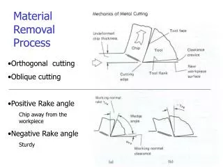
Reasons for this enhancement of hot cracking susceptibility in laser welds Osaka University Generally speaking, decreasing the welding heat input is one of the most effective countermeasures for preventing hot cracking. From this reason, laser welding is a preferable safeguard against this problem, because it can provide a lower welding heat input. However, hot cracking susceptibility may be enhanced in some cases of the laser welding of stainless steels and nickel base alloys. There are two reasons for this enhancement: ■ Due to a characteristic shape of penetration in laser welds ; 'the key hole type of penetration. ■ Due to the rapid solidification and cooling that takes place during welding with an extremely low heat input.
Center-line crack Solidification crack at neck Inter-granular crack at well Hole by shrinking during solidification at bead center Liquation crack at neck in HAZ Types and positions of hot cracking in laser welds Osaka University Hot cracking susceptibility may be enhanced in laser welding due to a characteristic shape of penetration in laser welds. ■ In the case of the key hole type of penetration of laser welds, various types of cracking may be experienced. ■These types of cracking is caused by the strain concentration at the specific part in the welds or in HAZ ⇒ Lab. Material Joining Process
Crack Hot cracking susceptibility may be enhanced in laser welding Mechanism of solidification cracking due to the rapid solidification and cooling during welding. Osaka University Solidification brittleness temperature range (BTR) (the second reason) ■ In general, solidification cracking will develop under the condition that the thermal strain subjected to the welds exceeds more than the critical value that it can bear. That is, solidification cracking will occur when the strain curve during cooling intersect with the solidification brittleness temperature range ; BTR ■ In laser welding with a low heat input, the strain rate during cooling will increase, and consequently may enhance the hot cracking susceptibility. Local strain Strain (Cracking) (No cracking) TL TS Temperature Weld metal
60μm 60μm Relationship between laser traveling velocity and total crack length in laser welds (SUS316L (P+S:0.04%)) Osaka University ■ Evidently, an increase in the laser traveling velocity produces a greater susceptibility to hot cracking in laser welds. ■ In addition, note that as the laser traveling velocity rises, the location where hot cracks occur changes from the dendrite boundaries to the center line of the welds.
Theoretical analyses of the liquidus and solidus temperatures during laser welding Thermal elastic- plastic analysis Two major factors to influence hot cracking susceptibility in laser welds Osaka University BTR Local strain Strain (Cracking ) (No cracking) TS TL Temperature ■ The BTR in laser welds will vary because of changes in the liquidus and solidus temperatures due to the rapid solidification. ■ The strain rate in laser welds will also enhance due to rapid cooling.
BTR Strain(%) BTR BTR Strain(%) Strain(%) TL Ts TL’ TL’ Ts’ Ts’ TL Ts Temperature Temperature Temperature Estimation of BTR in laser surface melted region Effect of rapid solidification Osaka University Arc welding Laser welding Ts varied by micro-segregation of impurity elements TL decreases due to supercooling ■ Determined the BTR in laser welds by theoretical analyses of the liquidus and solidus temperatures based on the BTR for GTA welding obtained by the Varestraint test.
BTR Strain(%) BTR BTR Strain(%) Strain(%) TL Ts TL’ TL’ Ts’ Ts’ TL Ts Temperature Temperature Temperature Estimation of BTR in laser surface melted region Effect of rapid solidification Osaka University Arc welding Laser welding Ts varied by micro-segregation of impurity elements TL decreases due to supercooling modified KGT model ■ In order to estimate the liqudus temperature, we calculated the dendrite tip temperature (T*), which corresponds to the liquidus temperature through calculation by the modified KGT model.
BTR Strain(%) BTR BTR Strain(%) Strain(%) TL Ts TL’ TL’ Ts’ Ts’ TL Ts Temperature Temperature Temperature Estimation of BTR in laser surface melted region Effect of rapid solidification Osaka University Arc welding Laser welding Ts varied by micro-segregation of impurity elements TL decreases due to supercooling ■ To determine the solidus temperature, we have conducted a theoretical analysis on the effect of the micro-segregation of impurity elements during welding on the solidus temperature by using the data-base of Thermo-calc. Thermo-Calc@
Theoretical model for calculation for impurity elements segregation in solidification process Osaka University Distribution of S at liquid/solid boundary Non-equilibrium coefficientKnes Cs kes:Equilibrium coefficient, Rv:Solidification speed, Ds:Diffusion coefficient Diffusion in solid ■ In this analysis,assumed the morphology of a dendrite to be a hexagonal column and evaluated distribution of the solute concentration with a one-dimensional diffusion model in which the solute diffused in the direction perpendicular to the grain boundary⇒
BTR calculated in laser welds of SUS316L Osaka University 1.0 1.0 LTV (mm/s) LTV (mm/s) 20 20 0.8 0.8 40 40 60 60 0.6 0.6 Strain (%) Strain (%) 0.4 0.4 0.2 0.2 P : 0.03% P : 0.02% 0 0 1680 1640 1600 1560 1520 1680 1640 1600 1560 1520 Temperature (K) Temperature (K) ■ The solidus temperature in the laser welds is found enhanced with a rise in the laser traveling velocity due to the increase in the solidification rate. ■ On the other hand, the liqudus temperature in the laser welds decrease due to supercooling in laser welds⇒
Direction of the the strain analyzed at the surface of the welds Osaka University Laser traveling velocity : Increase Analysis point and direction θ=60° θ =50° θ=35° Calculated by Quick Therm 20mm/s 60mm/s 40mm/s ■ The thermal strain is another important factor to consider the occurrence of cracking in welds ■ Used the 3-dimensional thermal elastic-plastic software package "Quick Therm" to calculate the strain formed during welding in laser welds and analysed the strain which is perpendicular not only to the center line of the weld but also dendrite boundaries. Lab. Material Joining Process
Local strain at the center perpendicular to laser scanning direction Osaka University LTV : Laser traveling velocity (mm/s) 1.2 1.2 LTV=60 Center-line Dendrite boundary 1.0 1.0 LTV=60 0.8 0.8 (θ=60°) θ Strain (%) Strain (%) 0.6 LTV=40 0.6 LTV=40 0.4 0.4 (θ=50°) LTV=20 LTV=20 0.2 0.2 (θ=35°) 0 0 1650 1600 1550 1650 1600 1550 Temperature (K) Temperature (K) ■Examples of calculation which show that the change in the thermal strain occurring during solidification increases with increasing laser traveling velocities. ■In contrast, in the case of dendrite boundaries, the strain taking place with a laser traveling velocity of 40mm/s is larger than that under other conditions.⇒ Lab. Material Joining Process
Comparison between BTR and strain at the bead center perpendicular to laser traveling direction Osaka University 1.2 LTV = 40 mm/s LTV = 20 mm/s LTV = 60 mm/s 1 0.8 Strain (%) 0.6 0.4 Cracking Cracking 0.2 0 1650 1600 1550 1650 1600 1550 1650 1600 1550 Temperature (K) SUS316L 0.02% P+S LTV : Laser traveling velocity 0.04% P+S ■Examine the possibility of solidification cracking in laser welds by superimposing plots of the BTR and the strain produced during cooling in laser welds. ■When the laser traveling velocity is 40 or 60mm/s, the strain perpendicular to the center line of the welds crosses to the BTR, which means that solidification cracks will occur at the center of the welds in this laser traveling velocity range. Lab. Material Joining Process
Comparison between BTR and strain perpendicular to dendrite growth direction at dendrite boundaries Osaka University 1.2 LTV = 40 mm/s LTV = 20 mm/s LTV = 60 mm/s 1 0.8 Strain (%) 0.6 0.4 Cracking 0.2 0 1650 1600 1550 1650 1600 1550 1650 1600 1550 SUS316L Temperature (K) 0.02% P+S LTV : Laser traveling velocity 0.04% P+S ■ The strain curve estimated for dendrite boundaries crosses the BTR when the laser traveling velocity equals 40mm/s. ■ This result suggests that solidification cracks will occur at the dendrite boundaries in the welds in this laser traveling velocity range.⇒
Center-line cracking (Calculated) Comparison between measured and theoretically calculated conditions to occur cracking Osaka University Cracking at dendrite boundary (Calculated) 0.04 Crack (Center-line) P+S content (mass%) 0.03 Crack (Dendrite boundary) 0.02 No crack SUS316L 10 20 30 40 50 60 Laser traveling velocity (mm/s) ■Good agreement between these two conditions determined by calculation and experimentals. ■These results suggest that the cause of solidification cracking in laser welds is actually the increase in the strain rate during solidification, in spite of the fact that the BTR becomes narrower due to rapid solidification.
1000 Austenite (A) 0.1 F/MA 100 YAG welding Arc welding Ferrite (F) S+P+B (mass%) Solidification rate (mm/s) No crack Crack 10 0.05 1 FA AF 0 0.1 1.4 1.6 1.5 2.0 Cr/Ni-equivalent Creq/Nieq Enhanced susceptibility due to solidification mode shift Osaka University J.C.Lippold, Weld. J., 73-6 (1994) 129s-139s 1.8 ■There is another factor to be considered which may influence hot cracking susceptibility in austenitic stainless steels in laser welding. ■It is known that the solidification mode in austenitic stainless steel weld metals shifts from primarily ferrite to primarily austenite when the solidification rate becomes sufficiently high. Lab. Material Joining Process
1000 Austenite (A) 0.1 F/MA 100 YAG welding Arc welding Ferrite (F) S+P+B (mass%) Solidification rate (mm/s) No crack Crack 10 0.05 1 FA AF 0 0.1 1.4 1.6 1.5 2.0 Cr/Ni-equivalent Creq/Nieq Enhanced susceptibility due to solidification mode shift Osaka University J.C.Lippold, Weld. J., 73-6 (1994) 129s-139s 1.8 ■ Laser welding with a low heat input can provide in some cases such solidification condition to cause solidification mode shift. ■ Alloys solidified in primarily austenite mode is more sensitive than ones in primarily ferrite mode. ■ This is another reason for the increased hot cracking susceptibility of stainless steels in laser welding. ⇒ Lab. Material Joining Process
Condition for transition of solidification mode Osaka University In the case of T*γ>T*δ In the case of T*δ>T*γ AF mode FA mode ■ In general, the phase which has the higher dendrite tip temperature is more likely to be the primary phase on solidification. Therefore the solidification mode shift can be predicted if the dendrite tip temperature of each phase is known.
Theoretical model for dendrite growth Osaka University (modified KGT model) S.Fukumoto, W.Kurz, ISIJ Inter., 37-7 (1997) 677-684 S.Fukumoto, W.Kurz, ISIJ Inter., 38-1 (1998) 71-77 K :Partition coefficient R :Dendrite tip radius V :Dendrite growth velocity ΔT:Undercooling related to the tip radius G :Temperature gradient D :Liquid interdiffusion coefficient P :Peclet number Iv(P):Ivantsov's solution ξc :Absolute stability coefficient mv,i:Velocity dependent liquidus slope Γ:Gibbs-Thomson parameter Dendrite Tip Temperature:T* ■Used the modified Kurz-Giovanola-Trivedi (KGT) model, which was extended to multicomponent alloys by Kurz in order to calculate the dendrite tip temperature. ■According to the model, the dendrite tip radius, R, is expressed as a function of dendrite growth velocity, V, as shown in this equation . ■For multicomponent alloys, the dendrite tip temperature, T*, is given by this equation. ⇒ Lab. Material Joining Process
Effect of dendrite growth velocity on dendrite tip temperature of ferrite and austenite Osaka University 1750 1730 1710 Dendrite tip temperature (K) ■The dendrite tip temperature in austenite rises above that in ferrite at dendrite growth velocities exceeding 0.9mm/s. ⇒ 1690 1670 1650 1×10⁻² 1×10⁻¹ 1×100 1×101 1×10² Dendrite growth velocity (mm/s) 23Cr-9Ni-0.34N steel Lab. Material Joining Process
AF mode FA mode 15 Bead center AF FA 10 Laser traveling velocity (mm/s) 5 Predicted condition to yield crack 0 1.3 1.4 1.5 Creq/Nieq Comparison of calculated solidification mode change with experimental results in laser welds of stainless steel Osaka University ■By using the above mentioned results, you can also predict the risk of hot cracking by calculation assuming that the solidification mode change from FA to AF will enhance cracking susceptibility. ■For instance, this figures show the theoretically predicted transition line from FA to AF at the center part of the weld metals for nitrogen containing austenitic stainless steels.⇒ 23Cr-9Ni-0.34N steel Lab. Material Joining Process
Crack No crack 15 Bead center AF FA 10 Laser traveling velocity (mm/s) 5 Predicted condition to yield crack 0 1.3 1.4 1.5 Creq/Nieq Comparison of calculated solidification mode change with hot cracking susceptibility in laser welds of stainless steel Osaka University ■The condition to yield AF mode coincide with the condition to occur hot cracking. ■ It means you can predict the risk of hot cracking through calculation of the mode shift from FA to AF even in laser weld. ⇒ 23Cr-9Ni-0.34N steel Lab. Material Joining Process
Contents Osaka University 1. Background 2. Prediction of Degree of Embrittlement ■475 ℃Embrittlement ■Sigma Phase Embrittlement 3. Mechanism of Weld Cracking ■Solidification Cracking in Laser Welding ■Ductility-dip Cracking 4. Summary Lab. Material Joining Process
Mechanism of ductility-dip crack Osaka University ■Ductility-dip cracking can occur in various alloys which exhibit a loss of ductility below the solidus temperature, when they are subjected to a strain sufficient to produce cracking during cooling in welding. ■ A ductility-dip crack formed in weld metals is normally very small, and is sometimes called a 'micro fissuring'. ⇒ Ductility curve DTR BTR Strain ε3 ε2 ε1 Ductility-dip cracking Temperature Lab. Material Joining Process
Mechanism of ductility-dip crack Osaka University ■ Recently Invar alloy has attracted special interest as a suitable material for cryogenic applications, such as fuel transport pipes due to its low thermal expansion coefficient and good toughness at low temperatures. ■ Invar alloy is however, found to be very susceptible to micro fissuring in multi-pass welds of heavy sectioned pipes. But, the mechanism of micro fissuring in the weld metals of Invar alloys is still uncertain. ⇒ Ductility curve DTR BTR Strain ε3 ε2 ε1 Ductility-dip cracking Temperature Lab. Material Joining Process
Surface of weld metal of Invar alloy after triple bead longitudinal Varestraint Osaka University ■ Many cracks in original weld pass which was reheated by a subsequent pass. Cracks preferentially occurred along the columnar grains and/or around the center line of the original weld bead. Fe-36Ni alloy
Effect of weld thermal cycles on cracking susceptibility Osaka University 3 Double-bead Triple-bead 2 Total crack length (mm) 1 0 1100〜1200 1000〜1100 900〜1000 900〜800 Peak temperature range in HAZ (K) Fe-36Ni alloy (0.011%S) ■ The total lengths of the cracks in the triple-bead test were much greater than those in the double-bead test. We can see that this tendency predominated in the peak temperature range between 1000K and 1100K. Lab. Material Joining Process