Download
1 / 20
210 likes | 360 Views
Computernetze 1 (CN1). 4 Spanning Tree Protokoll 802.1D-2004. Prof. Dr. Andreas Steffen Institute for Information Technologies and Applications. B. B. A. A. What happens without Spanning Tree. No entry in lookup table or broadcasts. Broadcasts turn into packet storms.

E N D
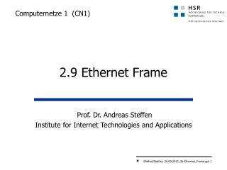
Computernetze 1 (CN1) 4 Spanning Tree Protokoll 802.1D-2004 Prof. Dr. Andreas SteffenInstitute forInformation Technologies and Applications
B B A A What happens without Spanning Tree No entry in lookup table or broadcasts Broadcasts turn into packet storms
Parallel Paths • Interconnected parallel paths between two LAN segments cause • endless circling of broadcast frames • endless circling of unicast frames during flooding phase • blocking of buffer resources • Closed loops in more complex topologies cause • overflow of all buffer resources and stagnation of the LANs • Broadcast storms • Solution to avoid these effects • Spanning Tree Protocol (STP)
B Root A Spanning Tree Basics F F A switch is elected as root F F A ‘tree-like’ loop-free topology is established Loop-free connectivity F F B F X F orwarding B locking
Spanning Tree • Spanning Tree Protocol (STP): • guarantees that there is always exact one path between any 2 stations • is implemented by a special protocol that is used for communication among the bridges by exchanging BPDU (Bridge Protocol Data Unit) packets with the MAC multi-cast address 01-80-C2-00-00-00. • active path failure causes activation of a redundant path • Main disadvantage of STP • redundant lines cannot be used for load balancing
Spanning-Tree Protocol OperationBridge Protocol Data Unit (BPDU) The BPDU is responsible for: • electing a root bridge • determining the location of loops • blocking to prevent loops • notifying the network of changes • monitoring the state of the spanning tree
802.1D-2004 Bridge Address and Bridge Identifier • 7.12.5 Unique identification of a bridge A unique 48-bit Universally Administered MAC Address, termed the Bridge Address, shall be assigned to each Bridge. The Bridge Address may be the individual MAC Address of a Bridge Port, in which case, use of the address of the lowest numbered Bridge Port (Port 1) is recommended. • 9.2.5 Encoding of Bridge Identifiers A Bridge Identifier shall be encoded as eight octets, taken to represent an unsigned binary number. The four most significant bits of the most significant octet of a Bridge Identifier comprise a settable priority component that permits the relative priority of Bridges to be managed. The nextmost significant twelve bits of a Bridge Identifier comprise a locally assigned system ID extension. The six least significant octets ensure the uniqueness of the Bridge Identifier; they shall be derived from the globally unique Bridge Address.
Parameters for STP • Bridge Identifier (Bridge ID) • combination of MAC-address and a priority number • priority number can be configured by the administrator • default 32768 • lowest Bridge ID has highest priority • lowest configurated priority number andlowest MAC-address • Port Cost (C) • costs in order to access local interface • inverse proportional to the transmission rate • original definition: cost = 1000 / transmission rate in Mbit/s • revised in 2001 and 2004 to accommodate higher speeds
Recommended Spanning-Tree Path Costs Link Speed Cost (32 bits) 802.1D-2004 Cost (16 bits) 802.1D-2004 Cost 802.1t-2001 Cost 802.1D-1998 ≤100 kb/s 200‘000‘000 65‘535 10‘000 10‘000 1 Mb/s 20‘000‘000 65‘535 1000 1000 10 Mb/s 2‘000‘000 65‘535 100 100 100 Mb/s 200‘000 65‘535 10 19 1 Gb/s 20‘000 1 20‘000 4 10 Gb/s 2‘000 2‘000 - 2 100 Gb/s 200 200 - - 1 Tb/s 20 20 - - 10 Tb/s 2 2 - - The path costs can be set to arbitrary values by the network administrator
Spanning Tree Process Steps Step 1: Electing a Root Bridge Step 2: Electing a Root Port on each non-root bridge Step 3: Electing a Designated Port on each LAN segment • All switches send out Configuration Bridge Protocol Data Units (Configuration BPDU’s) • BPDU’s are sent out of all interfaces every two seconds (by default - tunable) • All ports are in Blocking Mode during the initial Spanning Tree process (prior to 802.1D-2004only).
Parameter Example LAN 2 C=10 C=05 Bridge 3 ID = 45 Bridge 4 ID = 57 C=10 C=10 C=05 Bridge 1 ID = 42 LAN 5 C=05 C=10 Bridge 5 ID = 83 C=05 LAN 1 C=10 Bridge 2 ID = 97 LAN 3 C=05 C=05 LAN 4
F F 9 F F F 9 4 9 4 F F 8 F 4 F 5 5 8 4 F F 3 7 B B 7 B B 3 B B 7 2 7 5 B B 5 2 B B 7 B 0 0 0 0 0 0 0 0 0 0 0 Electing the Root Bridge LAN 2 C=10 C=05 Bridge 3 ID = 45 Bridge 4 ID = 57 C=10 C=10 C=05 Bridge 1 ID = 42 LAN 5 C=05 C=10 Bridge 5 ID = 83 C=05 LAN 1 C=10 Bridge 2 ID = 97 LAN 3 C=05 C=05 LAN 4
Election of the Root Bridge • Strategy to determine Root Bridge : • if bridge receives Configuration BPDU with lower Root Bridge ID as own Bridge ID, it aborts emitting own Configuration BPDUs on the concerned port, the received Configuration BPDU is passed on to all other ports • if bridge receives Configuration BPDU with higher Root Bridge ID as own Bridge ID, it continues emitting own Bridge ID as proposed Root Bridge ID via Configuration BPDUs on all ports the other bridges must give up
4 F 4 4 F 4 F F 4 4 F F B B 2 B 2 2 2 B 2 B B 2 0 0 0 0 0 0 Electing Root Ports LAN 2 C=10 C=05 R R Bridge 3 ID = 45 Bridge 4 ID = 57 C=10 Root C=10 C=05 Bridge 1 ID = 42 LAN 5 C=05 C=10 Bridge 5 ID = 83 R C=05 LAN 1 C=10 R Bridge 2 ID = 97 R= Root Port LAN 3 C=05 C=05 LAN 4
4 F 4 F 4 4 F F F 4 B 2 B 2 B 2 B B 2 2 10 10 10 5 5 Electing Designated Bridges LAN 2 C=10 C=05 R R Bridge 3 ID = 45 Bridge 4 ID = 57 C=10 Root C=10 C=05 Bridge 1 ID = 42 LAN 5 C=05 C=10 Bridge 5 ID = 83 R C=05 LAN 1 C=10 R Bridge 2 ID = 97 LAN 3 C=05 C=05 LAN 4
Spanning Tree applied III LAN 2 Root Path Cost 05 Root Path Cost 10 C=05 C=10 R R Bridge 3 ID = 45 Bridge 4 ID = 57 C=10 B D Root C=10 C=05 Bridge 1 ID = 42 Root Path Cost 00 LAN 5 C=05 B C=10 Bridge 5 ID = 83 Root Path Cost 05 R C=05 LAN 1 C=10 R Root Path Cost 10 B = Blocking Port D = Designated Port Bridge 2 ID = 97 LAN 3 C=05 C=05 LAN 4 D D
Root Port and Designated Bridge Election Rules • Every bridge computes • which of its ports has the lowest Root Path Cost • calculation based on sum of Root Path Costs received in BPDU plus port costs of interface which has received BPDU message • sum of all port costs from bridge over path to RB • this port becomes the Root Port • at equal costs the port ID decides (lower means better) • similar to Root Bridge selection • a Designated Bridge (DB) is selected for each LAN-segment • bridge with lowest Root Path Cost on its Root Port • at equal costs the bridge with lowest Bridge ID wins
Root Path Cost Determination Rules • Strategy for Root Port and Designated Bridge determination: • if a bridge receives a Configuration BPDU on a port which is closer to the Root Bridge • the own port costs are appended to this BPDU and then the BPDU is passed on to all other ports • closer means that the sum of Root Path costs received in the BPDU plus port costs of the receiving interface is lower than the actual Root Path Cost stored in the bridge • if a bridge receives a Configuration BPDU on a port which is more distant to the Root Bridge • the bridge emits the Configuration BPDU on the same port (which received the BPDU originally) but replaces the Root Path Cost with its own local stored cost • more distant means that the sum of Root Path costs received in the BPDU plus port costs of the receiving interface is higher than the actual Root Path Cost stored in the bridge
Bridge Port States • Blocking • Won’t forward frames; listens to BPDUs. All ports are inblocking state by default when the switch is powered up. • Listening • Listens to BPDUs to make sure no loops occur on the networkbefore passing data frames. Calculation of Topology • Learning • Learns MAC addresses and builds a filter table but does notforward frames. • Forwarding • Sends and receives all data on the bridged port.
Spanning Tree Summary • Purpose: To maintain loop-free topologies in a redundant layer 2 infrastructure • Provides path recovery services in case of componentor link failure • Original 802.1D-1998Spanning Tree Protocol (STP) • High availability was mediocre at best • Convergence time was quite slow (>50 seconds) • New 802.1wRapid Spanning Tree Protocol (RSTP) • Achieves significant improvements in reconfiguration speed and reliability by defining Backup and Alternate bridge ports in addition to Designated and Disabled bridge ports. • RSTP obsoleted STP in the IEEE 802.1D-2004 revision(chapter 17 RSTP completely replaced chapter 8 STP).