Download
1 / 44
870 likes | 2.54k Views
Sectional Views. Chapter 6. Objectives. Understand sections ad cutting-plane lines Apply correct section lining practices Recognize and draw section lining for ten different materials Draw a sectional view, given a two-view drawing. Objectives (cont.).

E N D
Sectional Views Chapter 6
Objectives • Understand sections ad cutting-plane lines • Apply correct section lining practices • Recognize and draw section lining for ten different materials • Draw a sectional view, given a two-view drawing
Objectives (cont.) • Demonstrate correct hidden-line practices for section views • Identify seven types of sections • Apply section techniques to create clear interpretable drawings • Demonstrate the proper techniques for sectioning ribs, webs, and spokes
Objectives (cont.) • Use hatching when using conventional breaks to show elongated objects • Interpret drawings that include sectional views
Understanding Sections • Section views have three main purposes: • Document the design and manufacture of single parts which are manufactured as one piece • Document how multiple parts are to be assembled or built • Aid in visualizing internal workings of a design
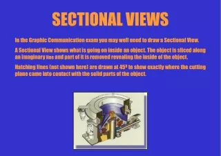
Full Sections • When a part is cut fully in half, the resulting view is called a full section • A line called the cutting-plane line shows where the object was cut and from which direction the section is viewed • The arrows point toward the section being viewed
The Cutting Plane • The cutting plane is shown in a view adjacent to the sectional view • In the section view, the areas that would have been in actual contact with the cutting plane are show with section lining • Those areas are cross-hatched
Lines Behind the Cutting Plane • The visible edges of the object behind the cutting plane are generally shown because they are now visible but they are not cross-hatched
Placement of Section Views • Section views can replace the normal top, front, side, or other standard orthographic view
Labeling Cutting Planes • When more than one cutting plane is used, it is especially important to label them for clarity
Line Precedence • When a cutting plane coincides with a center line, the cutting plane line takes precedence • When a cutting plane line would obscure important details, just the ends of the line outside the view and the arrows can be shown
Rules for Lines • Show edges and contours which are now visible behind the cutting plane • Omit hidden lines in section views • A section-lined area is always completely bounded by a visible outline
Rules for Lines • The section lines in all hatched areas for that object must be parallel • Visible lines never cross section lined areas
Cutting Plane Line Style • The preferred cutting plane line style is made up of equal dashes ending in arrowheads • Another style uses alternating long dashes and pairs of short dashes
Section Lining Symbols • Section lining symbols may be used to indicate specific materials • Using different section lining patterns helps you distinguish different materials, especially on assembly drawings • It is acceptable to use the general-purpose symbol at different angles for different parts
Half Sections • Objects that are symmetric can be shown effectively using a half-section • Half sections expose the interior for one half of the object and the exterior of the other half • One quarter of the object is removed
Half Sections • In general: • Omit hidden lines from both halves of a half section whenever possible • Use a center line to divide the sectioned half and the unsectioned half
Broken Out Sections • Sometimes only a partial section of a view is needed to expose interior shapes • Such a section, limited by a break line, is called a broken-out section
Revolved Sections • You can show the shape of the cross section of a bar, arm, spoke, or other elongated object by using a revolved section • The visible lines adjacent to a revolved section may be broken out if desired
Removed Sections • A removed section is one that is not in direct projection from the view containing the cutting plane • Removed sections should be labeled and arranged in alphabetical order from left to right
Offset Sections • In sectioning through complex objects, it is often desirable to show features that do not lie in a straight line by offsetting or bending the cutting plane • Offsets or bends in the cutting plane are all 90 • The bends in the cutting plane are never shown in the sectional view
Ribs in Section • To avoid a false impression of thickness and solidity, ribs, webs, gear teeth, and other similar features are not hatched with section lining even though the cutting plane slices them
Aligned Sections • When sectioning parts with angled elements, the cutting plane may be bent to pass through those features • The plane and features are then revolved into the original plane • The angle of revolution should always be less then 90 for an aligned section
Partial Views • If space is limited on the paper or to save time, partial views may be used with sectioning
Conventional Breaks and Sections • Cross-hatching is often added when showing a conventional break • Conventional breaks are used to shorten the view of an object • The breaks used on cylindrical shafts or tubes are often referred to as “S-breaks”
Assembly Sections • Section views are often used to create assembly drawings • Different parts use different hatch patterns • Solid features that do not have interior structure are not hatched