Download
1 / 45
450 likes | 583 Views
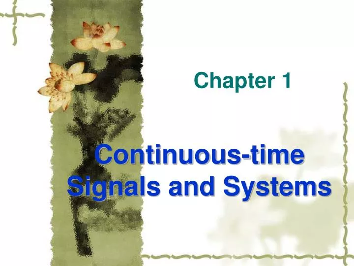
Chapter 1. Continuous-time Signals and Systems. y(t). f(t). h(t). §1 .1 Introduction. Any problems about signal analyses and processing may be thought of letting signals trough systems. From f(t) and h(t),find y(t), Signal processing. From f(t) and y(t) ,find h(t) ,System design.

E N D
Chapter 1 Continuous-timeSignals and Systems
y(t) f(t) h(t) §1.1 Introduction Any problems about signal analyses and processing may be thought of letting signals trough systems. • From f(t)and h(t),find y(t), Signal processing • From f(t) and y(t),find h(t),System design • From y(t) andh(t),find f(t), Signal reconstruction
§1.1 Introduction • There are so many different signals and systems that it is impossible to describe them one by one • The best approach is to represent the signal as a combination of some kind of most simplest signals which will pass though the system and produce a response. Combine the responses of all simplest signals, which is the system response of the original signal. • This is the basic method to study the signal analyses and processing.
§1.2 Continue-time Signal • All signals are thought of as a pattern of variations in time and represented as a time function f(t). • In the real-world, any signal has a start. Let the start as t=0 that means f(t) = 0 t<0 Call the signal causal.
u(t) u(t- t0) 1 1 0 t 0 t0 t Typical signals and their representation • Unit Step u(t) (in our textbook (t)) • u(t)is basic causal signal, multiply which with any non-causal signal to get causal signal.
Typical signals and their representation Sinusoidal Asin(ωt+φ) f(t) = Asin(ωt+φ)= Asin(2πft+φ) A - Amplitude f - frequency(Hz) ω= 2πf angular frequency(radians/sec) φ – start phase(radians)
Typical signals and their representation • sin/cos signals may be represented by complex exponential • Euler’s relation
Typical signals and their representation • Sinusoidal is basic periodic signal which is important both in theory and engineering. • Sinusoidal is non-causal signal. All of periodic signals are non-causal because they have no start and no end. f (t) = f (t + mT) m=0, ±1, ±2, ···, ±
α <0 decaying α 0 growing α =0 constant Typical signals and their representation • Exponential f(t) = eαt • αis real
Typical signals and their representation • Exponential f(t) = eαt • αis complex α = σ + jω f(t) = Ae αt = Ae(σ + jω)t = Aeσ t cos ωt + j Aeσ t sin ωt σ = 0, sinusoidal σ > 0 , growing sinusoidal σ < 0 , decaying sinusoidal (damped)
1 -τ/2 τ/2 Typical signals and their representation • Gate signal The gate signal can be represented by unit step signals: Pτ(t) = u(t + τ/2) – u(t – τ/2)
Typical signals and their representation • Unit Impulse Signal • δ(t) is non-zero only at t=0,otherwise is 0 • δ(t)could not be represented by a constant even at t=0,but by an integral. • Regular function has exact value at exact time. Obviously,δ(t)is not a Regular function.
4/τ 2/τ 1/τ 1/τ -τ/2 τ/2 -τ/4 τ/4 -τ/8 τ/8 Unit impulse function δ(t) • With a gate signal pτ(t), short the duration τ and keep the unit area When τ0,the amplitude tends to , which means it is impossible to defineδ(t) by a regular function.
Properties of δ(t) • Sampling Property Briefly understanding: • When t 0, δ(t)=0, thenf(t)●δ(t)=0 • When t = 0, f(t) = f(0) is a constant. Based on the definition of δ(t), it is easy to get:
δ(t) δ(t- τ) τ 0 t 0 t Properties of δ(t) • δ(t)shift • δ(t)times a constant A: Aδ(t) Ais called impulse intension which is the area of the integral
Properties of δ(t) • Differential of δ(t)is also an impulse δ’(t) = dδ(t)/dt and • Integral of δ(t)is unit step signal:
Properties of δ(t) • δ(t)is a even function, that is δ(t) = δ(-t) We got δ(t)from a gate signal, and gate signal is an even function. It is also easy to give the math show of the even property.
f(t) kΔτ §1.3 signal representation based on δ(t) • Any signal can be represented by a shifted weight sum of δ(t) Approximate f(t) with a serial of rectangles. For the rectangle near t=kΔτ , the duration is Δτ, the high is f(kΔτ ), and the area is f(kΔτ )Δτ . So the rectangle can be represented by f(kΔτ )Δτ δ(t - kΔτ ).
§1.3 signal representation based on δ(t) f(t)can be approximated as follows: The smaller of , the higher of the accuracy, and when d, k , the above expression becomes precision representation:
f(t) y(t) §1.4 Linear time-invariant system Signal f(t)pass though system, output y(t): f(t) y(t) If satisfy af(t) ay(t) and f1(t) + f2(t) y1(t)+ y2(t) That is af1(t) +b f2(t) ay1(t)+ by2(t) The system is called linear.
§1.4 Linear time-invariant system If satisfy f(t – t0) y(t – t0) The system is called time-invariant. The reason to study linear time-invariant system is that based on δ(t) shifted and weighted sum representation of f(t), we can only discuss the system response for unit impulse,then make the sum of responses for all shifted and weighted impulses to get the whole response. It can be done only with linear time-invariant systems.
δ(t) h(t) §1.5 System unit impulse response The system response for unit impulse δ(t) is called system unit impulse response, and denoted as h(t) h(t) is important figure of linear time-invariant system. It can be done to get response for any input signal based on h(t), because any signal can be represented as shifted and weighted sum of δ(t).
§1.5 Signal pass through linear time-invariant system δ(t) h(t) aδ(t – t0) ah(t – t0) Denote y(t) = f(t) * h(t), which is called convolution of f(t) and h(t)
Frequency domain analyses of continue-time signals and systems
Analyses in time domain and frequency domain • With the time domain analyses, signals are decomposed the sum of shifted and weighted δ(t) , and only system response for δ(t)is attracted attention. • With the frequency domain analyses, signals are decomposed the sum of fundamental sinωt and harmonious, and the system response for sinωtcould be attracted attention only.
§1.6 Fourier series of periodic signals • Periodic signals is expanded to Fourier series The average in one period
§1.6 Fourier series of periodic signals • Fourier series in exponential form
f(t) A - τ/2 τ/2 t -T T §1.6 Spectrum of periodic signals • Periodic rectangles with period T, duration τ, and amplitude A:
Sampling function Sa(x) = sinx/x Fn = (Aτ/T)Sa(nω0 τ/2)
ω0= 2π/T §1.7 Fourier analyses of non-periodic signals—Fourier Transform When the period of a periodic signal is expanded to ∞, the signal is becoming non-periodic: But T , Fn and ω0 0,the amplitude of lines and the distance between lines tend to 0. It is unreasonable to describe the signal with frequency lines. So the concept of spectrum density is introduced.
1 -τ/2 τ/2 F(jω) τ ω 2π/ τ 4π/ τ §1.8 Fourier Transform of typical signals • Gate
e-at u(t) t |F(jω)| 1/a ω §1.8 Fourier Transform of typical signals • Exponential f(t) = e-at u(t) a>0
δ(t) 0 t |F(jω)| 1 t ω 0 §1.8 Fourier Transform of typical signals • Unit impulse δ(t) Unit impulse has uniform frequency density in whole frequency range, that means it has infinite wide band.
§1.9 Fourier Transform of typical signals • Constant 1 1 2πδ(ω) This result could be got directly based on the symmetry of Fourier Transform. Constant 1 represents direct current signal, and its spectrum is non-zero only at ω = 0, which is a δ(ω)
F[cos ω0t] F[sin ω0t] (π) (π) (jπ) ω0 -ω0 ω0 -ω0 (-jπ) §1.9 Fourier Transform of typical signals • Sin and cos function Based on the transform pair 1 2πδ(ω) and δ(t) 1, we have some important conclusions: F[ejω0t] F[cosω0t]= F[(ejω0t + e-jω0t)/2]= π[δ(ω + ω0)+ δ(ω - ω0)] F[sin ω0t]= F[(ejω0t - e-jω0t)/2j]= jπ[δ(ω+ ω0)- δ(ω - ω0)]
ω0δω0(ω) δT(t) -2 ω0 - ω0 0 ω0 2 ω0 ω -2T -T 0 T 2T t §1.9 Fourier Transform of typical signals • Unit impulse sequence ω0 = 2π/T
§1.10 Properties of Fourier Transform • Linear Fourier Transform is an integral, and it is a linear operation: If f1(t) F1(jω) f2(t) F2(jω) Then af1(t) + bf2(t) aF1(jω) + bF2(jω)
§1.10 Properties of Fourier Transform • Time shift Signal’s shift in time domain equals phase shift in frequency domain f (t - t0) F(jω)e-jωt0 Based on the definition of Fourier Transform, the above result is easy to be shown.
§1.10 Properties of Fourier Transform • Frequency shift(Modulation theorem) Modulate carrier sinω0t with base band signal f(t) Based on definition of Fourier Transform: f(t)ejω0t F[j(ω – ω0)] With Euler’s relation, it is easy to show: f(t) cosω0t = 1/2 f(t) (ejω0t +e-jω0t ) f(t) cosω0t 1/2 {F[j(ω + ω0)]+ F[j(ω – ω0)]} f(t) sinω0t j/2 {F[j(ω + ω0)]- F[j(ω – ω0)]}
Pτ(t) F(jω) τ 1 -τ/2 τ/2 1/2 {F[j(ω + ω0)]+ F[j(ω – ω0)]} Pτ(t) cosω0t τ/2 -ω0 ω0 Spectrum of amplitude modulation
§1.10 Properties of Fourier Transform • Energy theorem W is energy of signal, |F(jω)|2 named signal energy spectrum is signal energy in unit frequency band that has similar shape with |F(jω)|, but no phase information.
§1.10 Properties of Fourier Transform • Convolution theorem • convolution theorem in time domain f1(t)*f2(t) F1(jω) F2(jω) • convolution theorem in frequency domain f1(t) f2(t) 1/(2π)F1(jω) *F2(jω) Transfer the convolution operation in one domain to the algebra operation in another domain. Almost all of the properties discussed above could be shown based on the convolution theorem: • Time shift: f (t - t0) = f (t )*δ (t - t0) F(jω)e-jωt0 • Frequency shift: • f(t)ejω0t 1/(2π)[F[j(ω )* 2πδ(ω -ω0)]=F[j(ω – ω0)]
f(t) h(t) H(jω) y(t) F(jω) Y(jω) §1.11 Fourier analyses of linear system • H(jω) is called system function, or transfer function y(t) = f(t) * h(t) Y(jω) = F(jω) H(jω) • Spectrum analyses is an active research area today.If system is too complicated to be represented by analytical expression, it could be done that input sin signals with different frequencies and measure the system output, then give the system transfer function.