Download
1 / 34
340 likes | 593 Views
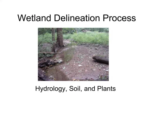
Floodplain Delineation of Indiana Streams. Allison Craddock Tom Gormley Jessica Tempest Erin Wenger. Problem Statement.

E N D
Floodplain Delineation of Indiana Streams Allison Craddock Tom Gormley Jessica Tempest Erin Wenger
Problem Statement Flooding due to recent development in rural areas of Indiana has heightened public concerns and requires the development of flood plain mapping in previously unmapped areas.
Objectives • Create a hydraulic base model • Delineate areas most prone to flooding • Design a flood control structure to reduce area of impact • Recommend the next course of action
Methods • Analyze topographic data to determine representative cross sections • Determine 100 year flow data from government resources • Obtain bridge data from Highway Department • Insert data into Hec-Ras • Based on output, design flood control structure
Why Use HEC-RAS? • Hec-Ras, developed by the Army Corps of Engineers, is the standard model used for floodplain delineation. • Performs one dimensional hydraulic analysis for steady and unsteady river systems. • Energy loss is calculated using Manning’s Equation.
Inputs Flow Data Drainage area Discharge Cross Section Data Manning's “n” Station/Elevation Bridge Information Height Restrictions Outputs Cross Section Plots Rating Curves Detailed Tabular Output at a Specific Cross Section Water Surface Elevation Flow area of channel Total Discharge HEC-RAS
Sensitivity Analysis • Flow rate, location of bank station, and Manning’s “n” value for both were varied to see the results of the change on velocity, top width, and elevation. • These values were chosen due to their variability in Hec-Ras.
Results of Sensitivity Analysis • Velocity and top width proved to be the most sensitive for flow rate. • Analyzed inputs have a minimal impact on elevation.
Calibration • The field data used was a floodway/flood boundary map for a reach directly above and adjacent to the model. • A top width was measured off the flood map and used to compare to the top width predicted by the model. • The model was calibrated coarsely first by varying the flow rate into the cross section. • Once the top width was close to the observed value, an attempt was made to refine the calibration using Manning’s n value on both the stream channel and the banks.
Results of Calibration Top width measured: 312.5 ft
Case Studies Jordan Creek – Allison Craddock Burnett Creek – Tom Gormley Haw Creek – Jessica Tempest Indian Creek – Erin Wenger
Jordan CreekGeographical Data 2 mile reach extending south from State Road 26 Township 23 N, Range 5 W, Tippecanoe County, Indiana Model acts as a southern continuation of Green Meadows residential development analysis
Model should be able to couple with preexisting HEC-2 data north of SR 26 Creek bed experiences a fluctuation in topography along its path, moving from a narrow V-shape to wide, low sloping terrain To minimize flooded areas, a levee will be constructed primarily on the eastern side of the creek, and the creek bed will be excavated further Reshaping of creek area should not have a negative impact on the local ecosystem, and alleviation of flooding in one area should not encourage flooding or erosion in other areas. Design Considerations
Cross Sectional Analysis and Design Before: Shallow side of creek will flood during a 100 Year storm. After: Construction of a levee combined with trenching and widening of creek results in usable land.
Results • Flooding area is minimized • Land previously in danger of flooding as well as newly constructed levee may be used to expand local agricultural practices • Erosion by flooding is kept to a minimum
Pre Design • During a 100 year storm, • the waterway splits at • the I-65 overpass. • By reshaping the channel • where the waterway splits, • the floodplain will be greatly • reduced. Channel Split Main Channel
Post Design • Soil will be taken from • various locations and used • in the reshaping of the land. • The dig areas will: • reduce erosion • decrease water elevation. • All soil will be excavated from • this location. New Channel
Recap of River Station 3508 After Design Before Design New Channel Excess Main Channel
Floodplain Map Note: Original Floodplain is based on Tippecanoe’s floodplain estimate found in Arcmap.
Final Results • All flow is contained within the channel. • The total land eliminated from the floodplain is estimated at 977.3 hectare. (2415 acres) • The land can now be used for development.
Haw Creek Site Characteristics • Approximately a 5 mile reach between Columbus and Hope, Indiana • Located in Township 10 N, Range 6 E, Bartholomew County • Connects Columbus FIS and Hope FIS models
Design Criteria • Significant flooding in the area between the 450 North Road Bridge and the 550 North Road bridge has caused loss in farmland. • To reduce flooding in this area, a levee will be constructed and the channel will be excavated to contain the flow in the channel in this area. • The effects of this design must not increase flooding at other locations along the stream. • Several cross section dimensions were modified to achieve the desired results.
Example of Modified Cross Section Before After
Floodplain Delineation Note: Delineation is based on 10 foot contour mapping.
Results • The flow was contained in the channel in the area of concern. • The velocity of the channel decreased in the area of modification due to an increase in volume that the new channel holds therefore erosion is not a concern. • The land previously in the floodplain can now be used for development purposes without the risk of flooding based on a 100 year storm.
Indian Creek Area of Study • Extends upstream 5.75 miles from the convergence with the Wabash River to join an existing DNR study • Township 23 N, Range 5 W, Tippecanoe County, IN
Current Situation • A residential area with bridge is threatened • Design must not interfere with housing or local bridge • Due to steep topography and high velocities in the channel, erosion is a concern
Recommendation • Selective stream bed modifications in the surrounding area can alleviate the flooding problems without interfering with the bridge. • The addition of vegetation and riprap will help decrease erosion.
Results • Local houses and pasture land are no longer in the flood plain • Bridge is not at full capacity • Erosion is keep to a minimum
Conclusion As seen in each of the four case studies, improvements in channel construction can help contain floods, reduce erosion, and optimize usable land.