Download
1 / 21
210 likes | 314 Views
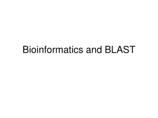
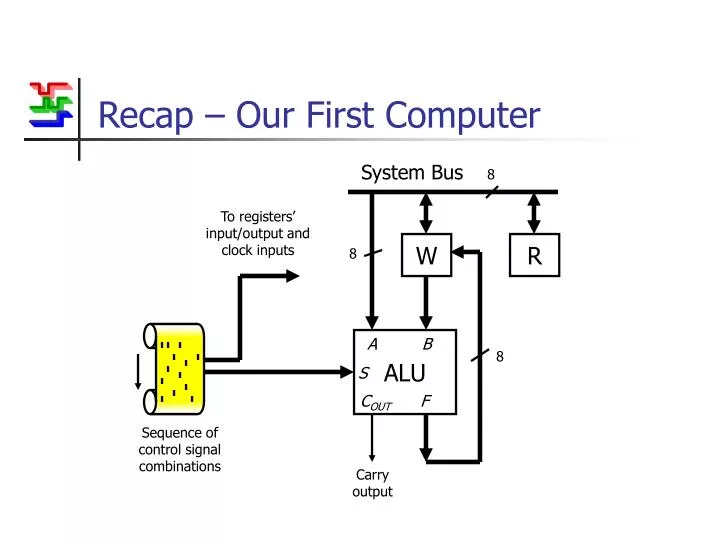
Recap – Our First Computer. System Bus. 8. To registers’ input/output and clock inputs. W. R. 8. ALU. A B. 8. S. C OUT F. Sequence of control signal combinations. Carry output. Updating the Paper Tape Approach.

E N D
Recap – Our First Computer System Bus 8 To registers’ input/output and clock inputs W R 8 ALU A B 8 S COUT F Sequence of control signal combinations Carry output
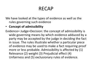
Updating the Paper Tape Approach • The paper tape programming method has a number of disadvantages • Not very quick or compact • Can’t randomly access (i.e. no jumps, loops etc.) • Requires a lot of bits of storage • Solid state program memory (a big bank of read-only registers) solves the first two problems • The last requires the introduction of operation codes (op-codes)
Solid-State Read-Only-Memory • Read-Only-Memory (ROM) can be thought of as a bank of registers • None of them can be written to (contents are fixed) • Only one can be read from at a time • That register is selected by an index number, its address Address in (No. of bits depends on how much memory there is) R.O.M. (No. of bits depends on how many control lines there are) Data out
A B C Control Unit CLK I/O CLK I/O CLK I/O I/O I/O I/O Op-Code Operation Codes • Useful operations • A ® B • B ® A • A ® C • C ® A • B ® C • C ® B • Only 6, could be coded into just 3 bits 8 System Bus
Op-Codes • The paper tape program can recreate absolutely any permutation of control signals, ALU inputs etc. • Many permutations are either not permitted or are just not very useful, so only a restricted set of possible data transfers are allowed. • This means that instructions can be coded into much shorter words, or op-codes (12 bits for PICs) • It does, however, require an extra block of logic to decode the op-codes.
Machine Code & Assembly Language • A sequence of op-codes forms a program • It is just a list of ones and zeros though, ideal for the processor – not so easy for humans • A program in this form is written in machine code • Each op-code has a mnemonic equivalent (e.g. ADD, SUB, OR etc.) • A program written in such mnemonics can be converted to machine code using an assembler • It is, therefore, known as assembly language
Examples • For the Z80 processor: Assembly Language Machine Code SUB B 10010000 OR C 10110001 LD D,E 01010011
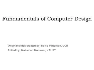
Using Program Memory Program Counter System Bus 8 To registers’ read/write and clock inputs W R 8 Program Memory ALU A B Control Unit 8 S COUT F Carry output
Using Program Memory Program Counter System Bus 8 To registers’ read/write and clock inputs W R 8 Program Memory ALU A B Control Unit 8 S COUT F Program Counter, PC Stores the position (or address) in program memory of the next instruction. It is automatically incremented after each operation. Carry output
Using Program Memory Program Counter System Bus 8 To registers’ read/write and clock inputs W R 8 Program Memory ALU A B Control Unit 8 S COUT F Program Memory A block of programmable read-only memory (ROM) containing a list of op-codes, i.e. a program. Carry output
Using Program Memory Program Counter System Bus 8 To registers’ read/write and clock inputs W R 8 Program Memory ALU A B Control Unit 8 S COUT F Control Unit A block of logic that translates the op-code into the corresponding ALU select inputs and the control signals to the registers. Carry output
More on the Program Counter • The Program Counter is a special purpose register used to address program memory. • After each instruction, its contents are incremented by one. • It can also be written to using the system bus, allowing the processor to ‘jump’ to any address in program memory. • Its contents can also be temporarily stored on a stack allowing easy implementation of sub-routines.
Pipelining • With this architecture, a typical instruction cycle consists of several stages: • Increment program counter • Wait for program memory propagation delay • Wait for control unit propagation delay • Set tri-state port on appropriate register to be read from • Wait for ALU propagation delay • Trigger working register to store result • This adds up to a significant delay • To speed things up, some of the operations can be started during the previous instruction cycle • This is known as pipelining
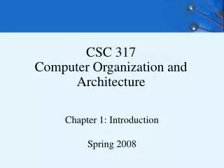
Instruction Register Program Counter System Bus 8 To registers’ read/write and clock inputs W R 8 Program Memory ALU A B Instruction Register Control Unit 8 S COUT F Instruction Register A special register whose only purpose is to temporarily store the op-code of the instruction currently being executed. The next instruction is fetched whilst the current one is executed. Carry output
Pipelining implications • Whilst each instruction is being executed, the program counter and program memory are fetching the next one • At the end of the instruction cycle, the next op-code is loaded into the instruction register • If the instruction was a jump: • The contents of the instruction register will not be valid and must be ignored • It will take another instruction cycle to fetch the valid code from the correct part of program memory • Jump instructions, therefore, take an extra cycle to complete
The Status Register (SR) • The ALU produces a variety of flags after most operations, the most important are: • Carry Flag • Zero Flag • The states of these flags are stored in the status register, SR. • This register can be read like any other. • More usefully, some operations (usually jumps) can be conditional on the state of one or more flags. • Using these op-codes, ‘if-then’ operations, ‘for’ loops etc. are possible.
Input/Output Registers • Input/Output (I/O) registers behave just like general purpose ones… • … except that I/O registers can be written to or read from externally via the pins of the chip housing the micro-controller. • The pins are configured as tri-state ports, i.e. they can input or output. • These registers are vital, they’re the only way the device can communicate and do something useful.
Programming • Micro-controller op-codes represent very simple operations: • Data transfers • Arithmetic or logical operations • Flow of control (manipulating the program counter) • Even the most elaborate of tasks can be broken down into a sequence of these primitive operations. • Breaking down jobs in such an elemental way is what programming is all about.
Part One of EE1A2 • Number Systems • You should be able to: • Convert numbers between decimal, hex and binary forms • Perform binary arithmetic operations • Binary Arithmetic Circuits • Adder, carry look-ahead • Addition/Subtraction Circuit • ALUs • Design of basic logic devices capable of a several binary arithmetic and/or logical operations.
Part One of EE1A2 (cont) • Registers • Memory elements storing one byte of data. • Interconnection using tri-state ports connected to a common bus. • Control signals necessary to transfer data. • Micro-controllers • All the basic components required to make a computer integrated onto a single chip. • The ALU, registers, program memory and input/output circuitry – what they all do. • Programming using assembly language - welcome to the rest of the course !