Download
1 / 91
920 likes | 1.18k Views
Data Link Layer Services and Protocols. Arzad A. Kherani (alam@cse.iitd.ac.in) Dept. of Computer Sc. And Engg. Indian Institute of Technology Delhi. Outline. Frame encoding Error detection and recovery Data Link Protocols Protocol analysis Performance Verification for correctness.

E N D
Data Link Layer Services and Protocols Arzad A. Kherani (alam@cse.iitd.ac.in) Dept. of Computer Sc. And Engg. Indian Institute of Technology Delhi Topics in Networking
Outline • Frame encoding • Error detection and recovery • Data Link Protocols • Protocol analysis • Performance • Verification for correctness Topics in Networking
Data link services • Operates between two neighboring devices • Provides a capability for higher-layer entities to send “packets” • A packet is a sequence of bits, with well-identified “start” and “end” • The packet is itself encapsulated into a “frame”, adding to it “header” and “trailer” Topics in Networking
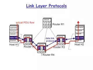
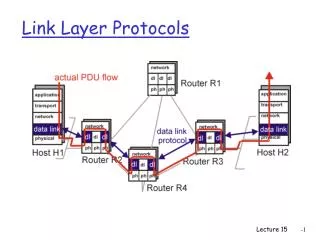
Service boundary Network layer Data link layer Physical layer Data link protocol Data link services (2) Topics in Networking
Data link services (3) • There is one data link for each physical link • In a router, for instance: Topics in Networking
Data link services • Connection-less service • Un-acknowledged service • Useful in case of low errors, and for real-time applications • Acknowledged service • Used in wire-less networks • Frames that are not acked may be re-sent • Connection-oriented service • acknowledged • Ensures delivery of frames Topics in Networking
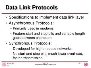
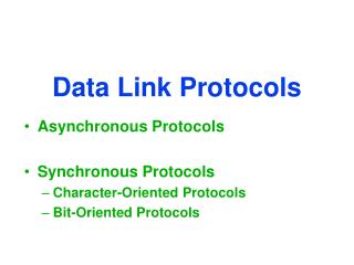
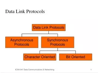
Framing • Link layer packet = frame • Problem: how to recognize beginning and end of frame? • Three methods • byte counting (DDCMP) • bit stuffing (X.25 Level 2, 802.x) • byte stuffing (BISYNCH, IMP-IMP) Topics in Networking
Framing • Solution based on counting bits/characters Topics in Networking
Framing • Solution based on flags (01111110) and bit stuffing Original bit string Bit string, suitably bit-stuffed Received, interpreted bit string Topics in Networking
Bit Stuffing (2) • Frame beginning and end marked by special bit string ( 01111110) • If 5 1's in data to be sent, sender inserts 0 • If receiver sees 5 1's check next bit(s) • if 0, remove it (stuffed bit) • if 10, end of frame marker (01111110) • if 11, error (7 1's cannot be in data) Topics in Networking
Framing • Solution based on flag characters, byte stuffing • Specialcharacters used for control Topics in Networking
Byte Stuffing Problems • Dependence on fixed character set • Must examine every byte of data on sending and receiving (insert / remove DLE) • Was used widely in IBM bisynch (at 9600bps) Topics in Networking
Error detection and recovery • Two approaches: • error correction codes • quick, but ineffective in several cases: • temporary dislocation • frame size is large, and error rate is high • burst errors • expensive • error detection and recovery using re-transmission • the preferred solution today • efficient Topics in Networking
Error detection • Hamming distance between pair of codes let message of length m 2m distinct messages with r redundant bits, codeword is of length n = m + r hamming distance between codes x, y = no. of bits in which x and y differ • Hamming distance for a code consider n dimension space, with 2m codewords hamming distance for code (or coding scheme) = minx, y (no. of bits in which x and y differ) Topics in Networking
d d Hamming codes • Hamming distance for code based on parity bit is 2 • resulting capability: detect 1 error, correct 0 errors • Result: • to detect d errors, the Hamming distance must be d+1 • to correct d errors, the Hamming distance must be at least 2d +1 Topics in Networking
Hamming codes (2) • Consider 7 bit data, 4 redundancy bits, codeword is 11 bits • message bits are numbered 3, 5, 6, 7, 9, 10, 11 • redundancy bits are numbered 1, 2, 4, 8 check bit 1 checks error in bits 1, 3, 5, 7, 9, 11 check bit 2 checks error in bits 2, 3, 6, 7, 10, 11 check bit 4 checks error in bits 4, 5, 6, 7 check bit 8 checks error in bits 8, 9, 10, 11 or (it should be) 0 = b1 + b3 + b5 + b7 + b9 + b11 0 = b2 + b3 + b6 + b7 + b10 + b11 0 = b4 + b5 + b6 + b7 0 = b8 + b9 + b10 + b11 Topics in Networking
Error detection using block codes • Block of data is re-written as a matrix, say 4 x 8 • last row is parity bits • bits are transmitted row-by-row, including parity bits • code is capable of detecting a burst of errors of length n Topics in Networking
x Xr /G(x) M(x) Xr M(x) R(x) T(x) = Xr M(x)-R(x) - 0 Yes no error No error = /G(x) R(x) = T(x) + E(x) Polynomial codes • Also known as Cyclic Redundancy Codes (CRC) • Note, all arithmetic is modulo-2 Topics in Networking
Polynomial codes (2) • Error detection capability depends upon G(x) • 1 bit error R(x) = T(x) + xi R(x)/G(x) = 0 iff E(x)/G(x) = 0 E(x)/G(x) 0 if G(x) has 2 or more terms single errors can always be detected • Similarly, two errors can always be detected if G(x) does not divide xk + 1 • Again, if G(x) is divisible by x+1 then an odd number of errors can be detected • Polynomial codes with r CRC bits will detect all bursts of length r or less • etc., etc. Topics in Networking
Polynomial codes (3) • International, IEEE standards • IEEE 802 standard G(x) = x32 + x26 + x23 + x22 + x16 + x12 + x11 + x10 + x8 + x7 + x5 + x4 + x2 + x1 + 1 it is capable of detecting bursts of length up to 32, and all odd number of errors, and even no of error with high probability Topics in Networking
Error recovery • Error detection, followed by re-transmissions, etc. • Efficient • Simultaneously address problem of “flow control” Topics in Networking
Network entity Network entity p1, p2, p3, .. p1, p2, p3, .. Data link entity Data link entity Physical layer Elementary data link protocols • Broad objective of data link protocol: • Error-free, loss-free, duplication-free and in-sequence transfer of user data packets between network entities • flow-controlled • transfer user data packets in both directions Topics in Networking
Network entity Network entity Data link entity Data link entity Physical layer entity Physical layer entity sender receiver Full-duplex channel receiver sender Data link modules Topics in Networking
Network entity Network entity Data link entity Data link entity Physical layer entity Physical layer entity sender receiver HALF-duplex channel Data link modules • We consider several protocols. But to begin with we consider moving data in one direction, only Topics in Networking
Data link protocol • Assumptions: • errors during transmission • processing capacity at receiver end • buffer capacity at receiver end • whether the underlying physical channel is half- or full-duplex • we will make nice assumptions to begin with, but move towards realistic assumptions later Topics in Networking
F_1 F_2 F_3 F_4 Sender, A Receiver, B Simple data link protocol: Utopia • Assume no errors, infinite processing capacity and buffer space at receiver end, and half-duplex channel Note, F_i: Data link frame, containing data packet, i Topics in Networking
Simple data link protocol: Utopia (2) • The sender’s end Topics in Networking
Simple data link protocol: Utopia (3) • The receiver’s end Topics in Networking
Definitions of data types/structures Topics in Networking
Definition of procedures Topics in Networking
Network entity Network entity Physical layer Simple data link protocol: Utopia (4) Topics in Networking
Rate rcvr can handle Acceptable rate time Flow control: problem and its solution • Flow control --> limit the rate at which a sender can send data to one which is consistent with the receiver’s ability to process incoming data • Two approaches to solving it: • rate-based: determine the minimum rate at which receiver can process incoming data • feedback based: send more data as when receiver can handle more data Topics in Networking
F_1 ack F_2 ack F_3 ack Sender, A Receiver, B Stop and wait protocol • Assume no errors, FINITE processing capacity, FINITE buffer space at receiver end, and half-duplex channel • ? Note, F_i: Data link frame, containing data packet, i Topics in Networking
Network entity Network entity Physical layer Stop-n-wait protocol (2) Topics in Networking
PAR protocol for noisy channels • PAR protocol addresses: • flow control • noisy channel • based on “positive acks” and re-transmissions Topics in Networking
F_1 ack F_2 F_2 Timer runs out Timer runs out ack F_3 ack F_3 ack Sender, A Receiver, B PAR protocol Topics in Networking
F_0 ack F_1 F_1 Timer runs out Timer runs out ack F_0 ack F_0 ack Sender, A Receiver, B PAR protocol • Data Frames are suitably numbered 0, 1, 0, 1, … • Acks are not numbered Topics in Networking
PAR protocol (sender) Topics in Networking
PAR protocol (receiver) Topics in Networking
Network entity Network entity Physical layer PAR protocol Topics in Networking
Pkt 1 F_0 Pkt 1 ack F_0 ack Timer runs out Pkt 2 F_1 F_0 Pkt 3 ack Pkt 4 F_1 Pkt 4 ack Receiver, B Sender, A PAR protocol • If the underlying physical layer is full-duplex, then the protocol fails Topics in Networking
Timer runs out Timer runs out Alternating bit protocol F_0 Pkt 1 • PAR protocol, with numbered acks Pkt 1 Ack_0 Pkt 2 F_1 F_1 Pkt 2 Ack_1 Pkt 3 F_0 Pkt 3 Ack_0 F_0 Ack_0 Sender, A Receiver, B Topics in Networking
Alternating bit protocol Topics in Networking
Alternating bit protocol Topics in Networking
Alternating bit protocol • Two possibilities: Topics in Networking
Alternating bit protocol • Use link A B to carry data from A to B, and acks from B to A and use link B A to carry data from B to A, and acks from A to B • Piggyback acks onto data frames, if one has data to send • Else, just an ack • Redundant acks are OK • An ack takes the form “I am waiting to receive data frame no. X” • Introduce a field for frame type, “data frame” or “ack frame” Topics in Networking
Performance of PAR protocol • Link utilization Utilization = L / (L+b*R), where L = size of data frame b = data rate R is round-trip delay • For a satellite channel, let L = 10K bits, b = 100 Kbps, R=500ms Utilization is 10K / (10K + 50K) = 1/6 • For a fibre-optic channel, let L = 10K bits, b = 100 Mbps, R = 1ms Utilization is 10K / (10K + 100K) = 1/11 • Delay=BW product is the key • Let sender send many data frames before it receives an ack Topics in Networking
Pipelining • Problems arise when one or more packets are lost Topics in Networking
Pipelining, with error recovery • Two approaches to recover from loss of data frame: • go-back n • selective repeat Topics in Networking
Pipelining, with error recovery • Go-back n scheme: Topics in Networking