Download
1 / 23
240 likes | 340 Views
The Microprocessor-based PC System. Microprocessor Course Electrical Engineering Department University of Indonesia. Bus, Memory & I/O Section. Fig. 1.2 shows the general block diagram of the PC A bus is a set of common connections that carry the same type of information

E N D
The Microprocessor-based PC System Microprocessor Course Electrical Engineering Department University of Indonesia
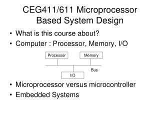
Bus, Memory & I/O Section • Fig. 1.2 shows the general block diagram of the PC • A bus is a set of common connections that carry the same type of information • The memory system is divided into three main parts: TPA, system area, XMS (optional) • The pentium Pro-based computer system, for example, can have up to 1M less than 4G or 64G of extended memory (Fig. 1.3)
Bus, Memory & I/O Section (cont’d) • The Transient Program Area (TPA) holds the OS and other program that control the computer system • It also stores any currently active or inactive application programs • The length of TPA is 640 KB • The memory map (fig. 1.4), hexadecimal addr.) shows how many areas of the TPA are used for system programs, data, and drivers
Bus, Memory & I/O Section (cont’d) • The interrupt vectors access various features of the DOS, BIOS (Basic I/O System), and application • The BIOS and DOS communications areas contain transient data used by program to access I/O devices and internal features of the computer system • The IO.SYS is a program that loads into the TPA from the disk whenever an MSDOS or PC DOS system is started
Bus, Memory & I/O Section (cont’d) • The MSDOS (PCDOS) program occupies two areas of memory • The size of the driver area and # of drivers change from one computer to another • The COMMAND.COM program controls the operation of the computer from the keyboard • The free TPA area holds application prog-rams as they are executed
Bus, Memory & I/O Section (cont’d) • The system area (Fig. 1.5) contains program on either a read-only memory or flash memory and also areas of read/write (RAM) memory for data storage • The area at locations C8000H-DFFFFH is often open or free. It is usually used for the Expanded Memory System (EMS) -> Fig.1.6 • The EMS allows a 64 KB page frame of memory to be used by application programs
Bus, Memory & I/O Section (cont’d) • The input/output space extends from I/O port 0000H to port FFFFH. • An I/O port is similar to a memory address but addresses an I/O device • The I/O area contains two major sections (Fig 1.7): • the area below I/O location 0500H is reserved for system devices • the remaining area is available I/O space for expansion
The Microprocessor • The microprocessor is the controlling element in a computer system and is sometimes referred to as the CPU (Central Processing Unit) • Memory and I/O are controlled through instructions that are stored in the memory and executed by the microprocessor • The microprocessor performs three main tasks for the computer system:
The Microprocessor (cont’d) • Data transfer between itself and the memory or I/O systems • simple arithmetic & logic operations (Table 1.3) • program flow via simple decisions • Why the microprocessor is powerful? • Able to execute millions of instructions per second from a program or software (group of instructions) stored in the memory system • able to make simple decision, based upon numerical facts (Table 1.4)
Buses • The microprocessor controls memory and I/O through a series of connections called buses • A bus is a common group of wires that interconnect components in a computer system • Buses select an I/O or memory device, transfer data between an I/O device or memory and the microprocessor, and control the I/O and memory system
Buses • Three buses exist for the transfer of information: address, data, control (Fig 1.8) • The address bus requests a memory location from the memory or an I/O location from the I/O devices • Table 1.5 depicts a complete listing of bus and memory sizes on the Intel family of p • Figure 1.9 shows the memory width and sizes of 8086-80486 and Pentium p
Buses • The memory sizes and organizations differ between various member of the Intel p familiy • The control bus contains lines that select the memory or I/O and cause them to perform a read or write operation. • Four control bus connections: MRDC, MWTC, IORC, IOWC
Buses • The micro-instructions for READ: • the p reads the contain of memory location by sending the memory an address through address bus • the p sends the memory read control signal (MRDC) to cause memory to read data • the data read from the memory are passed to the microprocessor through the data bus