Download
1 / 19
210 likes | 327 Views
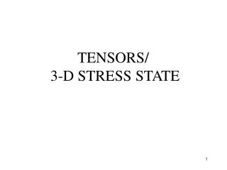
STRESS STATE 2- D. Stresses acting on an elemental cube. It is convenient to resolve the stresses at a point into normal and shear components.

E N D
Stresses acting on an elemental cube It is convenient to resolve the stresses at a point into normal and shear components. The stresses used to describe the state of a tri-dimensional body have two indices or subscripts. The first subscript indicates the plane (or normal to) in which the stress acts and the second indicates the direction in which the stress is pointing. Figure 3-1 Stresses acting on an elemental cube.
Description of Stress at a Point • As described in Sec.1-8, it is often convenient to resolve the stresses at a point into normal and shear components. In the general case the shear components are at arbitrary angles to the coordinates axes, so that it is convenient to resolve each shear stress further into two components. The general case shown in Fig. 3-1. • A shear stress is positive if it points in the positive direction on the positive face of a unit cube. (It is also positive if it points in the negative direction on the negative face of a unit cube.)
Figure 3-2. Sign convention for shear stress (a) Positive; (b) negative
Two Dimensions Figure 3-3 Forces and Stresses related to different sets of axes.
With the coordinate system shown, the stress s, acting in a direction parallel to F across area A is simply F/A. Because F has no component parallel to A, there is no shear stress acting on that plane. Now consider a plane located at angle which defines new coordinates axes in relation to the original x-y system. The forces F has components Fy’ and Fx’ acting on the plane whose area A’ equals A/cos . Thus, the stresses acting on the inclined plane are: and • The developments leading to Eqs. (3.3) and (3.4) have, in effect, transformed the stress yto a new set of coordinates axes. (3.1) (3.2)
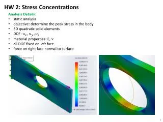
Figure 3-4. The six components needed to completely describe the state of stress at a point. • If the three components of stress acting on one face of the element are all zero, then a state of plane stress exists. Taking the unstressed plane to be parallel to the x-y plane gives (3.3)
Rotation of Coordinate Axes • The same state of plane stress may be described on any other coordinate system, such as in Fig. 3.5 (b). • This system is related to the original one by an angle of rotation q, and the values of the stress components change to , , and in the new coordinate system. • It is important to recognize that the new quantities do not represent a new state of stress, but rather an equivalent representation of the original one. • The values of the stress components in the new coordinate system may be obtained by considering the freebody diagram of a portion of the element as indicated by the dashed line Fig. 3.5 (a).
(a) (b) Figure 3-5. The three components needed to describe a state of plane stress (a), and an equivalent representation of the same state of stress for a rotated coordinate system (b)
The resulting freebody is shown in Fig. 3.6. Equilibrium of forces in both the x and y directions provides two equations, which are sufficient to evaluate the unknown normal and shear stress components and on the inclined plane. • The stresses must first be multiplied by the unequal areas of the sides of the triangular element to obtain forces. • For convenience, the hypotenuse is taken to be of unit length, as is the thickness of the element normal to the diagram.
Figure 3-6. Stresses on an oblique plane Summing the forces in the x- direction, and then in the y-direction, gives two equations. (3.4) (3.5)
Solving for the unknowns s and t, and also invoking some basic trigonometric identities, yields The desired complete state of stress in the new coordinate system may now be obtained. Equations 3.6 and 3.7 give and directly, and substitution of q + 90o gives . (3.6) (3.7)
Figure 3-7. Stress on oblique plane (two dimensional) Let Sx and Sy denote the x and y components of the total stress acting on the inclined face. By taking the summation of the forces in the x direction and the y direction, we obtain or
The components of Sx and Sy in the direction of the normal stress s are and so that the normal stress acting on the oblique plane is given by (3.8)
and since and The shearing stress on the oblique plane is given by (3.9) The stress may be found by substituting q+p/2 for q in Eq. (2-2), since is orthogonal to (3.10) Equation (3.10) to (3.12) are the transformation of stress equations which give the stresses in an coordinate system if the stresses in the xy coordinate system and the angle q are known.
To aid in computation, it is often convenient to express Eqs. (3.10) to (3.12) in terms of the double angle 2q. This can be done with the following identities. The transformation of stress equations now become (3.11) (3.12) (3.13)
It is important to note that . Thus the sum of the normal stresses on two perpendicular planes is an invariant quantity, that is, it is independent of orientation or angle q. 1. The maximum and minimum values of normal stress on the oblique plane through point O occur when the shear stresses is zero. 2. The maximum and minimum values of both normal stress and shear stress occur at angles which are 90 degrees apart. 3. The maximum shear stress occurs at an angle halfway between the maximum and minimum normal stresses. 4. The variation of normal stress and shear stress occurs in the form of a sine wave, with a period of q = 180o. These relationships are valid for any state of stresses.
Poisson’s ratio is defined as the ratio between the lateral and the longitudinal strains. Both 11 and 22 are negative (decrease in length) and 33 is positive. In order for Poisson’s ratio to be positive, the negative sign is used. Hence, = - 11 = - 22 3333 (3.1) Figure 3-2 Unit cube being extended in direction Ox3
Since V=Vo (3.2) • Substituting Eq. 3.2 into Eq. 3.1, we arrive at • = 0.5 • For the case in which there is no lateral contraction, is equal to zero. Poisson’s ratio for most metals is usually around 0.3